When designing and installing I/O cards considering wall process stations, we must take into account some restrictions. A detailed description is given in the WAGO I/O System 750 Design Guidelines. In particular, the following rules apply:
A maximum of 64 I/O cards with a width of 12 mm can be connected to one processor module.
But we probably won't reach this limit, because we'll probably hit the max. limit of physical data points sooner:
One processor module can be connected to approx. 300 – 400 inputs or outputs.
This limit is set so that the application program is not too large and the program cycle does not last longer than hundreds of milliseconds. However, the number of physical data points also depends on the technology: if, for example, it is only a matter of collecting binary signals, such as monitoring protection states, it is possible to connect twice as many I/O points. On the contrary, if zone controllers are integrated into the processor module and almost each of them has its own weekly time program (which takes up a relatively large amount of space in the memory), the total number of data points will be lower, for 50-60 controllers it can be, for example, 250-300 physical data points.
Cards with a maximum total consumption of 1650 mA can be connected to one processor or power supply module.
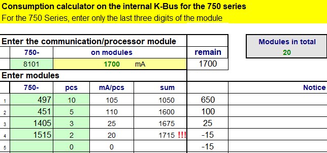
We can easily calculate the load of the module using the load calculator, available at domat-int.com website in the Downloads - Technical documentation - For designers section. In column B, enter the last three- or four-digit number of the communication card, and in column D, the number of pieces on the bus. Column H shows the remaining current for the following cards. If the result is negative, we have to remove the cards and insert the power module 750-613.

Card configuration where we already have to use another power module.
In this situation, we would have to insert a power supply module between the two 750-1515 modules and apply 24 V to it from the source. We then perform the same calculation for the cards following the power supply module.
The entire set is finished with the 750-630 card.
Other cards can be added to the pre-prepared wMX, wMX/COM, wCIO and wCIO/COM sets. However, the above restrictions still apply.
For the 750-652 communication cards, we have to calculate the integrated variables into the data points.
There are usually a maximum of 4-5 RS232/RS485 communication cards in the set, again this is a so-called "soft limit", it depends on the number of connected devices and the number of data points on each bus. More complex systems are recommended to be consulted with Domat technical support.
These cards must work in client mode, i.e. serial servers (frequency converters, zone controllers, etc.) are connected to their communication terminals. If we need to share data with a foreign system via a serial line in a connection where the PLC is in the role of a server, it is necessary to use the onboard port for this purpose (found in w750-8102 and wCIO/COM, wMX/COM assemblies). Integrated variables are counted in the total number of inputs and outputs, since the "bottleneck" here is the internal bus between the cards and the processor module.
If a GSM modem is used in the set for sending alarm SMS, it must be connected to the onboard port. We can supply the serial cable to connect the modem on request, it is a non-crossed DB9 M-M cable, which is not a commonly produced type. It is advisable to write it in the specification so that it is ordered during implementation.
When expanding the number of I/Os, new cards are always added to the end of the assembly.
In principle, the order of the cards does not matter, it does not matter whether the first analog inputs or other types of signals are in the set (from left to right), etc. From the point of view of EMC and the clarity of the connection, it makes sense to merge the same types of data points together, i.e. if we have, for example, 3 cards DO, we place them next to each other and then continue DI and other types of cards. However, when the set is subsequently expanded to include additional cards, the new cards must be added to the end of the set, not between the existing cards. When the PLC starts, the cards are automatically addressed according to the positions starting from the processor module. If the original row was broken, the addresses of the existing cards would be changed, which would have to be fixed in software.
The DIN rail on which the modules are installed must be properly fixed and secured against bending.
It would be ideal to use the original WAGO DIN rail (210-114 /-197) with a height of 15 mm, which has a material with a thickness of 1.5 mm, or another rail with a height of 15 mm. Conventional slats with a height of 7.5 mm, made from material with a thickness of 1 mm, do not have sufficient rigidity for lengths greater than about 30 cm and must be fixed to the substrate in several places, ideally every 10 cm. The problem is that the latch of the components (cards) interferes with the profile of the support rail, and the mounting points (screw connections) must be recessed into the support rail - use countersunk screws or blind rivets.
 There is no longer room for the mounting screw heads between the bottom of the cards and the DIN rail.
If we used pan head screws and didn't countersink them into the rail, the cards could be pushed up and lose contact along the inner bus. Unfortunately, this leads to the interruption of communication between the processor module and the cards, and thus to the total loss of device functionality.
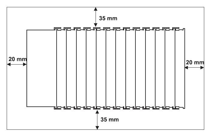
Sufficient space must be left around the assembly for heat dissipation.
 Minimum distances of the assembly from other components in the cabinet.
The free space is important not only for the removal of waste heat, but also for easier handling of the wires that come out of the sides of the cable ducts. If the prescribed distances were not observed, there would not be sufficient margin for routing the wires from the card terminals to the channels during installation and service work.
Card assemblies can be extended / split using module 750-627 and lan cable