When renovating transmission station networks in industrial areas, we may find ourselves in a situation where we need to connect modern process stations with an Ethernet network, but individual engine rooms have historically been connected either by a serial communication line (RS485) or even just by a telephone line. Laying a new line, typically an optical cable, is prohibitive in terms of price and sometimes even deadlines.
Some systems delivered today can communicate with each other and with the central office (SCADA) via serial lines, in addition to Ethernet, using standardized protocols - e.g. Modbus RTU, BACnet MS/TP, or company protocols. However, this solution brings considerable limitations. In addition to the significantly lower effective data transfer rate, we cannot use the bus for other services, for example service access to the PLC (exception is SSCP in Merbon PLC or native BACnet MS/TP), web access or connection of foreign systems via the Ethernet interface.
Sometimes the deployment of VDSL converters (ADSL successor) can help in these cases. These devices can act as a bridge from a network point of view: they connect two Ethernet networks (in our case two home stations) on the line layer, which means that they are completely transparent for IP communication and do not require any configuration. The connection between the converters requires a regular telephone cable, i.e. the twisted pair used for the RS485 bus is not even necessary. The result is a system of "point-to-point" Ethernet lines that are connected to each other in the machine rooms, to the PLC and possibly to other devices (operating terminals) using industrial switches.
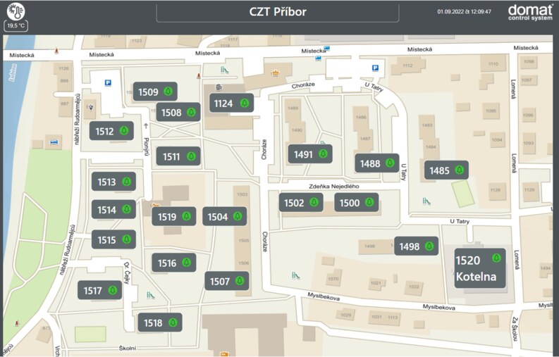
 Overview page of CZT Příbor in Merbon SCADA visualization
The used VDSL converters, Planet VC-231G, work in pairs. There are also central (e.g. eight-port) hubs that radially connect other stations – this option would be more advantageous in terms of the price of the components, but it is not feasible because of the original topology of the cables. The topology was a line, the cables were led from one station to another and the entire line ended in the boiler house. Due to the fact that there were more pairs in the cables and most of them were spare, it was possible to slightly change the topology during commissioning and thus achieve more favorable transmission properties.
VDSL converters are connected to the double line using an RJ11 connector, a classic telephone socket. Since the transmission speed achieved (and indeed the function of the converter in general) is significantly dependent on the quality of the line, we will use Wago clamps for the transition between the thin cable from the cord with the RJ11 connector to the fixed line. We definitely avoid common „chocolate“ terminal blocks or twisted connections. These are the source of unpredictable faults that can only appear over time and are manifested by irregular outages. In addition, Wago clamps are easy to disconnect repeatedly, which is advantageous for galvanic control of lines by blasting. It is advisable to prepare connecting cables in advance, which can be obtained by cutting the RJ11 telephone cords (usually included with VDSL modems) and tinning the wires at the free end of the cable.
During commissioning, we check the positions of the DIP switches. Default positions are ON, i.e. CPE (Slave), Interleave, Symmetric transmission and 8 dB. Usually, it is enough to switch DIP1 on the converter in Master role, we only change the other settings in case of problems.
DIP1 – CO or CPE
CO (Central Office) is Master, CPE (Customer Premises Equipment) is Slave. Roles relate to establishing communication and finding transmission parameters. On a double line, Master and Slave are always facing each other. The other parameters are set only on the converter with the Master role and the Slave only takes them over. That is why it is advantageous to have the masters in a place that is more accessible (for example, in a boiler room with visualization and not in an exchange station, located in another building under several locks or even with a mode access).
DIP2 – Interference Protection - G.INP or Interleave
G.INP is a technology that ensures immediate resending of a packet in case its transmission has been disrupted.
Interleaving consists of dividing packets into parts and reassembling them so that in the end the whole packets are more resistant to short-term interference - after reassembly, only a part of each packet is always broken, while the rest can be reconstructed thanks to redundancy. However, this data manipulation in principle always leads to a latency of up to 40 ms, which can negatively affect e.g. game applications or voice transmission.
Apparently, for less congested lines it is better to use G.INP, because packet repetitions do not occur so often that it has a negative effect on the overall throughput, and at the same time we avoid the latency that occurs with interleaving. However, if the line is of poorer quality, it is more convenient to use interleaving, because with G.INP the repetition of packets would be so frequent that the resulting throughput would be worse than the interleaving delay "by definition".
DIP3 – Band profile: symmetrical or asymmetrical
The asymmetric profile allows a different transmission speed for each direction of transmission. We would use it in the case where a significantly (by order of magnitude) higher transmission speed is permanently expected in one direction, for example, if the line is used exclusively for backup.
A symmetrical profile provides approximately the same throughput for both directions, which corresponds to the vast majority of applications.
DIP4 – SNR Margin 12 dB or 8 dB
Signal strength versus noise level. Better resistance to crosstalk is achieved with a higher signal-to-noise ratio (12 dB), but the transmission speed is then lower.
When designing a topology, we are limited by the existing network of communication cables. Since the quality and length of the line are decisive for the achievable transmission speed of the converters, we try to make the connection between individual Master - Slave pairs always as short as possible and, if possible, in one cable, without connecting multiple segments in series. It is the connections that are critical points and can cause temporary or permanent outages that are poorly diagnosed.
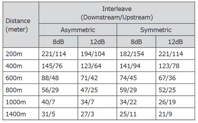
The maximum length of the connection between the converters is 1.4 km with a conductor diameter of 0.5 mm. The highest achievable transfer speeds depend on the length and quality of the line:
 Max. transfer rates in Mbps for Interleave mode. It is not significantly different for G.INP mode. Source: Planet Technology Corp.
In one place (node) there is the following composition of devices:
Connection diagram of two nodes
One pair of converters introduces a communication delay of approx. 14 ms. It is possible to arrange multiple connections in a row, we just have to calculate the sums of these delays. The latency to the visualization node (boiler = PC) looked like this:
Network topology, times at some nodes are the responses of the ping command to the PC
Each red link represents one pair of VDSL converters. In the housing network, the length of the connection did not exceed approx. 130 m, which is relatively little (the maximum allowed distance between transducers is 1400 m). The rather confusing connection of the nodes is due to the topology of the existing cabling, some cables only passed through certain nodes, etc. It would certainly be possible to design a topology that is more suitable in terms of the total length of the line, but in this case it was preferred that the existing cables were as undisturbed as possible.
The transmission speed was basically not important, since the communication between each PLC and the central PC needs tens or hundreds of kbps. While it is true that the closer the link is to the central office, the more data it carries, the values are updated in seconds, and even when uploading programs etc., there were no visible differences in network behavior compared to a regular 100 Mbps Ethernet network.
During the trial run in the summer of 2022, there were occasional outages and jamming of some network segments. The following measures helped:
The last but very important point is documentation: especially in the case of renovations, when the implementation project cannot cover all the changes and modifications that occur during commissioning, it is absolutely necessary to record all information in the actual execution project. This is in particular the following data:
High-quality documentation of the actual design is important not only for subsequent service, but also for troubleshooting during commissioning.