One of the most common errors when trying to send a SMS message over a GSM modem is Error 26, Timeout when executing AT command:

First, you can check that the SIM card works and supports sending SMS (not only for data). Sometimes the operator requires to make a call to activate the card in the system. So test the sim in the mobile, send an sms and if it's ok, continue with the modem. The main problem with the GSM modems over RS232 is that they mostly expect flow control - they use signals like RTS, CTS etc. Some PLCs have, because of number of available processor pins, only RX, TX, and GND available at their Cannon9 connectors. Controllers running on Linux, e.g. markMX, markMX2, mark320, etc. have these signals and it is only necessary to select RTS/CTS flow control in the IDE.
So, the first thing is to get the proper modem cable.
There are also Null Modem cables which cross the Rx and Tx signals, and are meant to connect two Terminal devices together (e.g. a PLC to another PLC, or a PLC to a M-Bus converter). They mostly do not work for connection between a PLC and a modem. The most common three types of null modem cables are as follows:

The Full Handshake Null Modem is most probably that one which can be bought as a ready-made Null modem cable. The Null Modem cables usually have female connectors at both ends.
However, to connect a modem to a PLC, a Modem cable is required. A standard modem cable has female and male connectors, and all its pins are brought through (1 to 1, 2 to 2, etc.). These cables can be got together with the GSM modem. For a Simple 3-wire Modem cable, three wires are enough (2 – 2, 3 – 3, 5 – 5), and the flow control signals are not connected.
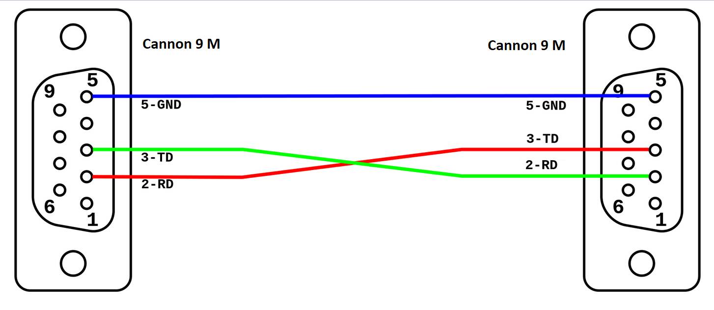
To connect the Wall .../COM PLCs (Wago) port to a GSM modem, a special cable must be built: DB9 male connectors at both ends, wired as 2-3, 3-2, 5-5:
Even if the standard Cannon 9M - 9F cable with all 9 pins through (1-1, 2-2, etc. ... 9-9) is used, the modem must be configured so as not to use flow control. This is because the signals at the PLC side are missing. The configuration is done using the AT\Q0 command. Note that there is a catch: a terminal (PC) which supports all flow control signals must be used, otherwise the modem can not be talked to at all. A standard USB-RS232 cable is usually OK.
Open a terminal program, e.g. hyperterminal from the old Windows, or any other you like, a commonly used one is terminal.exe (https://sites.google.com/site/terminalbpp/).
Set the proper serial parameters, such as 115200,N,8,1. (Some modems have autobaud, which means that they automatically recognize the baudrate and reply with no need for special settings.). Try to send the "AT"+Enter command, there should be a reply "OK". If you do not see what you write, go to settings and tick Echo - Type characters entered locally.
If you have got this far, enter AT&V to see the current settings:
Functional modem - something like this:
ACTIVE PROFILE:
 E1 Q0 V1 X4 &C1 &D2 &S0 \Q0 \V1
 S0:000 S3:013 S4:010 S5:008 S6:000 S7:060 S8:000 S10:002 S18:000
 +CBST: 7,0,1
 +CRLP: 61,61,78,6
 +CR: 0
 +FCLASS: 0
 +IFC: 0,0
 +ILRR: 0
 +IPR: 9600
 +CMEE: 1
 ^SCKS: 0,0
 OK
A modem which needs fixing:
ACTIVE PROFILE:
 E1 Q0 V1 X4 &C1 &D2 &S0 \Q3
 S0:000 S3:013 S4:010 S5:008 S6:000 S7:060 S8:000 S10:002
 +CBST: 7,0,1
 +CRLP: 61,61,78,6
 +CR: 0
 +CRC: 0
 +CMGF: 0
 +CNMI: 1,0,0,0,0
 +CMEE: 0
 +CSMS: 0,1,1,1
 +CREG: 0,1
 +CLIP: 0,2
 +COPS: 0,0,"T-Mobile CZ",0
 +CGSMS: 1
 +ICF: 3
 OK
There are differences in the \Q parameter setting:
To fix this, bring the modem to factory settings:
AT&F
and enter
AT\Q
(same as AT\Q0, without data flow control)
AT&W
(permanent writing of all current parameters to NVRAM)
Then, connect your cable and link your modem to the PC again.
It is a good practice to try to send the SMS manually from the terminal to see that it works. Follow the AT command set of your modem, usually a
AT+CMGF=1
press enter, it should write OK
AT+CMGS="phone_number"
press enter
enter text message
press enter
press Ctrl-Z
press enter
In the terminal, it looks like this: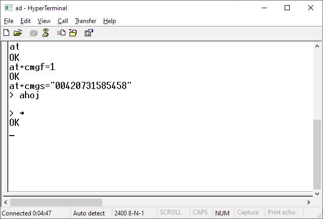
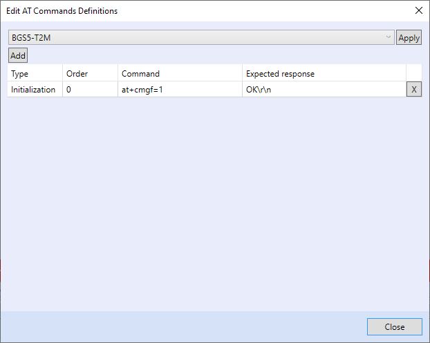
If the message arrives successfully, then it is a good time to try with PLC. Just remember to check the predefined command set and - if necessary - delete all commands except for the at+cmgf=1:
The messages should be sent correctly now.
An excelent tool for debugging is a serial spy, such as three CANNON connectors wired together:
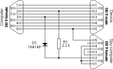
Works also with two LEDs rather than with a 1N4148 diode and a resistor; in fact, the LEDs are much easier to get.
There is no need to connect the 4,6,1 and 7,8 pins on the Spy socket – the terminals 2 (Receive Data) and 5 (Ground) connect the Spy connector to your USB-RS232 cable. Open a Terminal program in your PC and connect to the respective COM port. The terminal shows the communication between the "Computer" (in fact, PLC) and "Device" (in fact, a modem). It can be seen easily if all commands have beed answered correctly, and if not, where the problem is.
