CAUTION This procedure only applies to older SoftPLCs. Newer PLCs using Merbon software can switch to this mode automatically, more information in our tutorial.
The input / output modules (I/O modules) must be configured as part of the commissioning process. They must be addressed at Modbus, and at some types also measuring ranges for analogue inputs must be set. Most frequently, the I/O moduly are addressed and set up using the ModComTool software and a serial converter, e.g. Domat M080 or some other USB or RS232 to RS485 converter.
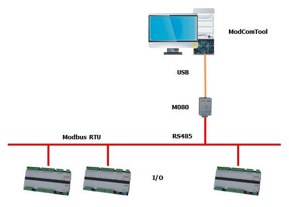 If the converter is not available or there is no serial port at the PC, it is possible to switch the MiniPLC into the Converter Mode. The PLC then does not execute the SoftPLC application which has been uploaded to it. It just works as an Ethernet / RS485 or RS232 converter. No other tools are necessary, for the configuration only a PC, Ethernet cable and a MiniPLC are needed.
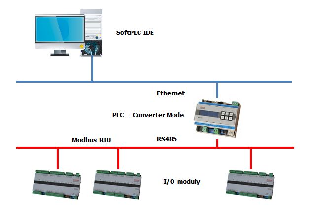 In the Converter Mode, there is a proprietary protocol between the client (here is is the SoftPLC IDE) and the MiniPLC in the Converter Mode. The protocol uses broadcasts. This means that it is not possible to use the ModComTool software for configuration of the I/O modules, and the SoftPLC IDE must be used instead. The proceeding is as follows:
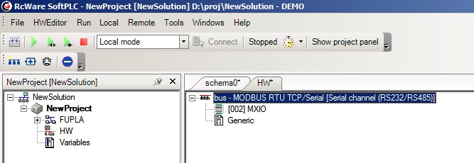
1. In SoftPLC IDE, define the I/O modules and their addresses together with configuration of analogue inputs and outputs. For MXPLC, the internal I/O module (MXIO) has Modbus address of 2 and is connected to COM port 3.
 2. Switch the PLC into Converter Mode:
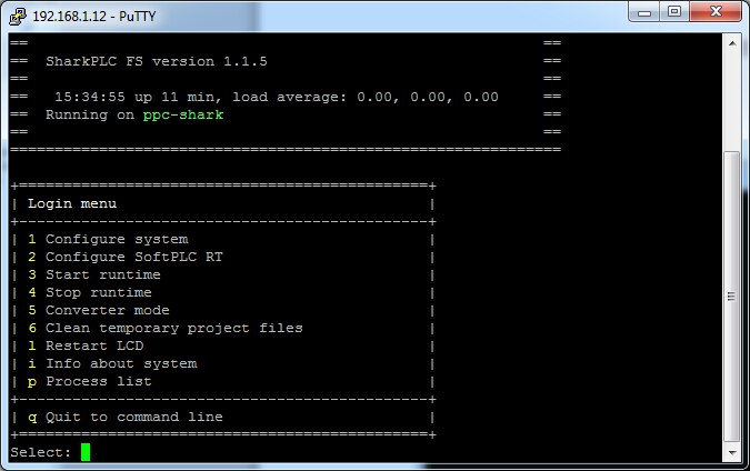 Select „4“ in the menu to stop the runtime. After the runtime has been stopped, select „5“ and wait for the message that the Converter Mode was activated. The Converter Mode can be terminated by hitting any key.
Switching into Converter Mode is indicated by three long beeps. The PLCs with a LCD display show the Converter Mode, serial port parameters and number of received packets from the Ethernet. The number of packets shows how many packets have been transferred from the PC to the MiniPLC, and their increasing number means a correctly working broadcast from the PC to the MiniPLC.
3. Right-click to channel, Edit, Channel properties. In the Development parameters select the COM port of the PLC to which the I/O modules are connected, and check Communicate through PLC.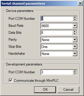 Click OK and confirm the dialogue with the channel name by OK, too. The Port COM Number in Development parameters has nothing to do with the PC COM ports, as the IDE in Converter Mode uses the ports of the PLC.
4. In the channel context menu select Special functions.
5. Click the Detect devices button to start bus scanning in the predefined address range. The last detected module is displayed as Last found. For a MXPLC, the dialogue looks as follows:
 Click Cancel to abort scanning at any time.
The Modbus address must be unique on the bus for a successful module detection. Hence, if there are more than a single module on the bus with factory default setings (Modbus address 1) and the modules should be addressed, all of them must be disconnected from the bus first, and then connected and readdressed one after another so that there never are two or more modules with the same address on the bus.
If the I/O module can not be detected, please check the following items:
6. Tick the scanned module (or more scanned modules) in the left part of the table, and click the Set ranges of AI/AO button. A confirmation window displays after the setting is performed.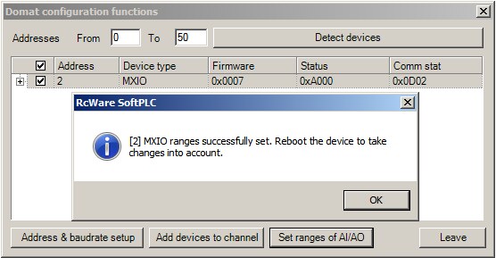 7. Click OK to scan the bus again. When addressing the modules, it is advisable to restart the I/O module prior to confirmation for the changes to apply.
8. Click the „+“ to see the set ranges of the analogue inputs and outputs.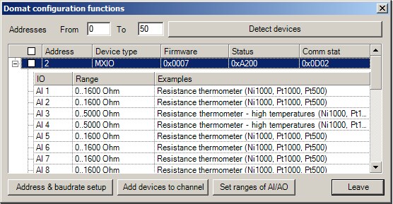 If the ranges were set using the Set ranges of AI/AO function, the setting should correspond with the I/O setting in the project in IDE:
Note that the I/O module switches between resistance measuring 0…1600 Ohm, 0…5000 Ohm, and voltage 0…10 V. The characteristics of the passive temperature measuring elements are set up in the IDE, because the linearisation is calculated in the application program rather than in the I/O module. The IDE reads just the resistance value from the I/O module. This is why e.g. in the example there is the same range at AI1 and AI2 even if the sensor types are different: Pt1000 and Ni1000(5000). The I/O module is set to resistance measurement 0…1600 Ohm for both AI1 and AI2.
9. After all modules are configured, switch the PLC from the Converter Mode back to normal operation again and restart; at IPLC500 and IPLC510 select „5“ in the terminal window to start the SoftPLC Runtime.