The PWM (Pulse Width Modulation) signal is well known in the art of communication. The value of the transmitted signal is "encoded" in the transmission by means of a two-state signal (voltage) as the ratio between the on/off states. This ratio is called a shift. The cycle in which one shift is transmitted is called the period, and it ranges in fractions of a second to microseconds. Using a PWM signal, a relative value in the range of 0 to 100% is transmitted. It is therefore a kind of very fast "flashing" with a variable flashing length and constant frequency. The PWM signal is used in radio engineering for modulation of the communication signal, in electrical engineering for power control of motors, dimmers and other power elements.
However, the PWM signal also occurs in a slightly different form in building management systems. It is used here to control thermally actuated valves. Here we should point out the difference between the drive:
Although thermal actuators are in principle also two-state control, because the signal takes on either the full value (24 V AC or 230 V AC, depending on the type) or 0 V, by "two-state control" we mean a system in which in which the drive is either fully open or completely closed at steady state. Pulse-modulated PWM control is sometimes also called quasi-continuous control because the analog signal is not used to transmit power and information, but this "flashing" with variable alternation. The PWM signal period is (unlike communication technology and industry) in building management systems several tens of seconds. This reduces the switching frequency of the power elements, which can have a positive effect on the radiated electromagnetic interference. Nevertheless, the thermal actuators work satisfactorily thanks to their longer time constant: the time required for a full valve stroke is between 2.5 and 6 minutes at 100% signal.
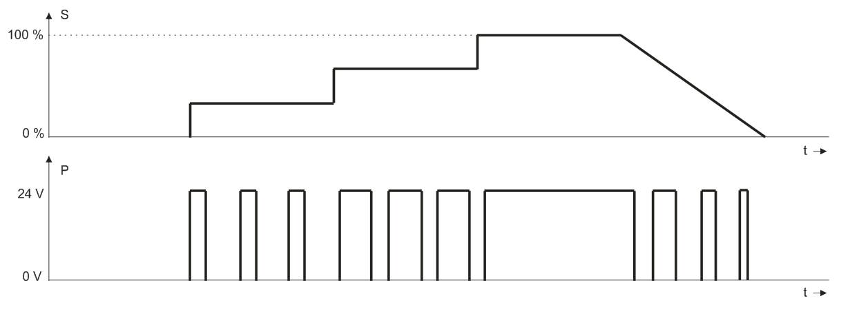 Fig. 1 - PWM signal, S: signal magnitude, P: PWM output voltage for 24 V AC
The principle of operation of the thermal valve is as follows: The heating element is heated by a passing current from the PWM control signal. The generated heat acts on an element made of a material with high thermal expansion, which changes its volume and presses on the valve stem the more it is heated. By changing the shift of the control signal, we can then change the degree of opening of the valve and thus the flow of heating or cooling medium essentially. The valves have a steady state consumption of around 3 to 6 VA, depending on the type, control force and control voltage.
An important feature of the thermal drive is the delay of the reaction when opening from a cold state. After connecting the supply voltage, it takes a minute or two for the drive to react and start moving - see the first part of the curves in Fig. 2, where we see that during the first 2.5 to 3.5 minutes, when the 100% signal is applied, valve completely closed. Only after the mechanism has warmed up does the stem start to move and the valve does not open completely until another tens of seconds. In practice, this phenomenon is unpleasant for heating convectors, which circulate cold air in the room for the first few minutes after the start of the transition from the attenuation mode to the day mode, which is not comfortable in the winter. As a countermeasure, either the drive is continuously preheated by intermittent pulses even in damping mode to reduce the ramp-up interval to a minimum, or a fan start delay of about 3 minutes is introduced, after which the valve is already at least partially open and hot flows in the register. water.
The thermal drive also has the property that it only works properly at ambient temperatures up to approx. 40 ° C. At higher temperatures, it is not guaranteed that the mechanism will be completely closed, as this may cause the valve to underflow. Therefore, be careful when installing actuators in distribution boxes and similar enclosed or thermally insulated spaces.
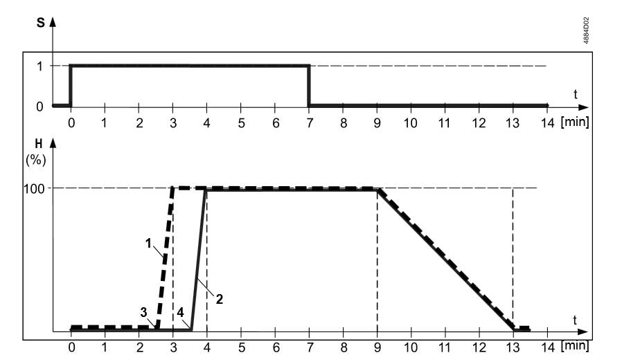 Fig. 2 - Valve stroke to actuator supply voltage over time. S: actuator voltage, H: valve stroke, 1: actuators at 230 V AC, 2: actuators at 24 V AC, 3.4: start of valve opening. (Source: Siemens)
The PWM signal can be found on electronic room thermostats, fan coil controllers, cooling panels and convectors, but also on output modules. A triac is usually used as a power member. When designing, we often address the question "how many valve actuators can be connected to one triac output?" Regulators usually have the maximum permissible triac current in the documentation. However, it is necessary to realize that thermal drives have several times less resistance in the cold than in the steady state, and therefore the initial current is several times greater than the continuous current. We must therefore respect this higher value of the initial current. When connecting multiple drives to one controller, we have several solutions:
When controlling several heaters with a single signal, the radiators do not work at full power most of the time. When heating at 20 to 30% of output, there may be a situation where, due to uneven hydronic conditions in the heating system, some of the bodies heat up a bit and some do not. The total power supplied to the room precisely covers the losses, so the regulation works properly. However, the user does not like this condition, because "some radiators do not heat" - against this, however, it is difficult to do anything other than enlightenment.
The control algorithm usually has a common PI characteristic, the requirement 0… 100% is fed to the PWM modulator, the output of which is controlled by a triac. However, good results can also be achieved with radiator control with two-state control with minimum hysteresis in tenths of K, mostly due to the inertia of the heating element.
During service and commissioning, we need to check whether the controller output provides an output signal. In doing so, the output must first be brought to the active state. This is usually done by increasing the setpoint (for heating) or decreasing it (for cooling). This works well for two-state or analog outputs, but for PWMs less than 100%, the state of the triac may still depend on what part of the period the output signal is currently in. In addition, the internal PI (D) algorithm can change the output signal so that a full signal (100%) appears at the output for up to a few minutes. Due to the length of the period (tens of seconds), it is easy to evaluate the state when there is no voltage at the output during the measurement, by mistake as a triac failure. Conversely, when measuring with high-impedance multimeters, we sometimes measure an oscillating voltage on a closed triac that is not connected to the valve drive, which may give the impression that the output is active. It is therefore recommended to use, for example, an LED diode with a series resistance of approx. 2k2 for 24 V AC or even better low-power indicator lamps (for 24 V or 230 V AC). Some drives, eg Siemens ASY23-LD, already have an indicator LED in the body, which lights up in the presence of control voltage. The light indication facilitates diagnostics even in cases where we check the voltage on the valve head, which is located at the opposite end of the room from the regulator. This reveals, for example, cut or incorrectly connected cables in the floor.
Some controllers (eg Domat UC100, UC200, FC010) also have a so-called resuscitation mode: if the control knob is pressed for a few seconds while the power supply is connected to the controller, the device switches to a state where the outputs are not controlled by control algorithms but manually - by setting the knob. In this way, we can manually bring each output to a permanently active state and conveniently measure the voltage on the drives. The activity of the outputs is also indicated on the LCD display. They can also be manually controlled by a relay for controlling the fan coil.
A common design problem is that the fittings, even with actuators, are supplied by a heating engineer or a supplier of convectors or fan coils - and the controller is supplied by the M&R profession. Then it is necessary to arrange an interface:
If control and measurement supplies actuators and fittings are supplied by other professions, the situation is more complicated and we have to specify:
Because thermal valves in installations are always present in larger quantities (in tens to hundreds of the same offices or rooms), each error entails high replacement costs and time losses due to delivery times.Because thermal valves in installations are always present in larger quantities (in tens to hundreds of the same offices or rooms), each error entails high replacement costs and time losses due to delivery times.
Special output modules, such as the Domat M312 with 8 triac outputs at 24 V AC, can facilitate work with PWM-controlled drives. After the RS485 bus with the Modbus RTU protocol, a value of 0… 100% is sent to the registers for individual outputs and the PWM signal is generated directly in the module. The default PWM signal period is 100 s, and this value can be changed via the bus. The M313 module is used to control heads with 230 V AC supply. The modules are especially suitable for installation in distribution boxes, because it is not necessary to route cables from the room controllers to the thermal drives that are installed in the boxes. Requests to open valves are read via the bus and sent to the module after communication using input-output variables.
Finally, it should be noted that actuators with a PWM signal are completely unsuitable for controlling the valves of air handling units with outdoor air treatment. For them, we need a reaction time in the order of max. Tens of seconds to guarantee the proper function of the frost protection. It is not a functional solution even for small units with valves, eg DN25, for which there are thermal actuators of appropriate dimensions and forces. Thermal actuators with a PWM control signal therefore provide a reliable and affordable solution for controlling zone devices, but only if they are properly designed, installed and commissioned.
