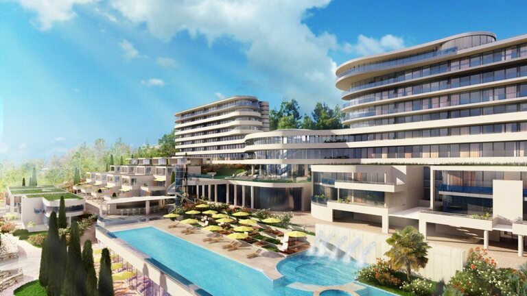
In 2020, our company created a measurement and regulation project for the construction of a building control system, which solves the automatic operation of ventilation, heating and air conditioning technology of this area.
These are mainly technologies of heating, cooling, air conditioning and climate control in individual rooms. To ensure the required technological parameters, signaling of operation and faults of 8 large HVAC units and four engine rooms for hot water production, the project proposes the use of our freely programmable control system. Autonomous technologies are data-integrated into the on-site measurement and control system using open protocols:
The project includes control, monitoring and data integration of beach, hotel, outdoor pool and villa equipment and addresses the following areas: field control level, ie peripherals and their installation on HVAC technology, control system (substation) for HVAC technology control (automation level), high-current technology installations and data integration of autonomous devices.
1. Heat/cold source
The heat/cold source for the building is a pair of water/water heat pumps, the source of which is seawater. Before starting these pumps, the seawater submersible pumps, condenser pumps and evaporator pumps are started (a total of 8 pumps). Seawater transfers heat or cold to technological heating or cooling water via exchangers located in the engine room. The process water is then fed via shut-off valves to a distributor/collector, from which the hotel and the congress center are fed.
For seawater treatment, a chlorinator is located in the engine room, from which the basic operating states and speed values of one of the submersible pumps can also be read. Other pumps are controlled via FM frequency converters located in the high-current switchboard, which is taken care of by DDC regulation. Setpoints for FM control are transmitted via data via MaR (LAN) communication. The primary heating/cooling water is fed to the engine room via three-way mixing valves. Heat pumps are data-integrated into the measurement and control system using the BACnet/IP protocol.
Cooling water from the evaporator side of the pump is led to the cold distributor/collector. On the manifold there are two pump branches for two-pipe change-over distribution for FCU hotel rooms, villas and air conditioning units. The branches for the two-pipe distribution to the FCU are equipped with shut-off flaps for redirecting cooling or heating water to the two-pipe distribution.
The heating water from the condensing side of the pump is led to the heating water distributor/collector. There are two flap-closed branches for FCU hotel and villas, one pump branch for air conditioning, one pump branch for heating the outdoor pool, one pump branch for heating the indoor pools and one equithermal mixing branch for underfloor heating. The heating water supply from the second heat pump can be redirected with shut-off dampers to heat the heating water storage tanks.
There are two boilers on the roof of one of the buildings, which are data-integrated into the building control system using the Modbus protocol. This boiler heater provides DHW heating, radiator heating and power supply to the heating water distributor/collector.
The whole system also regulates underfloor heating and pool water heating.
For some FCU and HVAC units, a four-pipe distribution is used to supply the heating and cooling medium. The exchangers on the mentioned devices are used for the common function of heating and cooling. To switch the flow of heating / cooling medium, a six-way valve with a continuous actuator with a 0-10 V control signal is installed in fan coil units, when at 5 V the valve for the appliance is closed, bands below and above 5 V are used for continuous regulation of heating sequence cooling.
In front of the heat exchanger units, intelligent pressure-independent two-way continuous control valves are installed for power control in the heating and cooling sequence in combination with two-state ball valves. Intelligent control valves are data-integrated into the MaR system via LAN and the BACnet IP protocol.
Frost protection of outdoor heating/cooling water distribution is ensured by an electric self-regulating heating cable.
2. Air conditioning
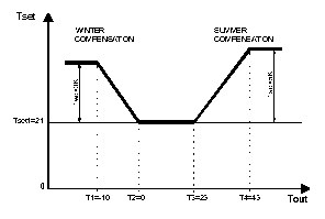
The required air temperature in the supply duct is regulated by cascade regulation, ie the required air temperature in the supply duct is determined on the basis of the difference between the actual and the required temperature in the exhaust duct resp. in space. This basic requirement is further corrected with respect to the outdoor temperature by a compensation curve and delimited by a selectable range of minimum and maximum values.
The reason for compensation in the summer is to save energy and prevent thermal shock when moving into and out of the building. In winter, a higher temperature of the blown air improves thermal comfort. The control elements of the air exchangers are then controlled so that this value is actually reached in the outlet channel.
3. System and communication
For local communication of the operator with the equipment of the control system, LCD graphic touch panels are located on the doors of the switchboards, where the basic parameters from the controlled technology can be read and set on them. The hotel's LAN data network is used for interconnection between individual switchboards.
A graphic control station is installed in the control room of the building for efficient management of the building. The software with which it is equipped enables fast and targeted monitoring and control of the BMS system using realistic graphics. A web server for remote control is also installed in the station. The selected data is available to other authorized users via the local network via a web browser. The entire measurement and control system can be easily expanded to other future investor requirements.
