In systems with fan coils, heat exchangers are often used alternately for heating and cooling. In a classic two-pipe connection with change-over, the whole building (or at least a branch) has to work with one type of energy - it can either heat or cool. In modern buildings, however, the requirements for heating and cooling in rooms are often very different or contradictory, and it is in these cases that the use of a four-pipe system with one exchanger can help. It is very elegant in these cases the use of a six-way valve. However, this requires a special control signal: in one 0 ... 10 V sequence, the part is reserved for heating and the part for cooling. There is a dead band between them. The sequence is therefore divided into three working parts:
The positions of the start and end points of the individual parts are determined by four constants. Their values are adjustable so that the output can be connected to any type of six-way valve actuator. In the Modbus table FCR013 we can find it in registers 149 to 152, for each output AO1 and AO2 separately.

Fig.: Heating and cooling sequence in the controller output signal
If we want the output AO1 or AO2 to work in the mode for the six-way valve, it must be set in the Modbus register 148. The default setting is 0.5 ... 4.5 V for heating and 5.5 ... 9.5 V for cooling. If neither the heating sequence nor the cooling sequence is active, the output is halfway between the zero values for heating and cooling, so by default it will be 5 V at the output. Each of the outputs has its own parameter settings. Details are given in the Modbus table FCR013. In the setting of the FCR013 controller, the voltage values are rounded to 0.1 V.
Different valve and actuator manufacturers have different actuator setting logics: sometimes the lower voltage range is for heating, other times for cooling, for some types of actuators the sequences can be reversed, usually by setting DIP switches. It is therefore a good idea to check the default settings of the drive before installation, and either adjust the parameters in FCR013 accordingly or describe the required settings on the drive in the implementation project.
For example, for the Siemens VWG41.20-1.6-2.5 (DN20) valve, the characteristic looks like this:
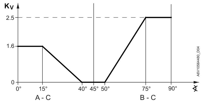
Fig .: Characteristics of the valve VWG41.20-1.6-2.5 (Source: Siemens)
Note that for heating (A-C) the valve has a different Kv value than for cooling (B-C). This is related to the heat output of the exchanger - during heating, the medium has a larger temperature drop and therefore a smaller flow rate is sufficient for the required output. The valve is used in conjunction with an actuator, eg GDB161.9E, whose dependence of the angle of rotation on the control voltage is linear. The valve has a 24 V supply, 0 ... 10 V control, an ASK77.3 adapter must be used.
The individual points for setting FCR013 and the drive 0 ... 10 V are then calculated as follows:
voltage [V] = angle [°] / 90 * 10
Similarly, the following relationship applies to the 2 ... 10 V drive:
voltage [V] = angle [°] / 90 * 8 + 2
and thus for GDB161.9E:
| point | angle | voltage for 0...10 V |
| H 100% | 15° | 1,66 V |
| H 0% | 40° | 4,44 V |
| C 0% | 50° | 5,55 V |
| C 100% | 75° | 8,33 V |
Tab.: Setting points FCR013 for VWG41.20-1.6-2.5 with GDB161.9E actuator
Attention, the valve of the same series, but with DN10, has a different characteristic! (The points are at angles of 15°, 30°, 60° and 75°, see the valve data sheet.) When designing and commissioning, always check this with the valve and actuator supplier and set the appropriate constants in the controllers accordingly. Belimo R30 ... B2 valves have the recommended cooling sequence as the first sequence to change. The table with parameters FCR013 then looks like this (suitable drive Belimo LR24A-SR is controlled by voltage 2 ... 10 V):
| point | angle | voltage for 2...10 V |
| H 100% | 90° | 10,00 V |
| H 0% | 60° | 7,33 V |
| C 0% | 30° | 4,66 V |
| C 100% | 0° | 2,00 V |
Tab .: Points for setting FCR013 for R30 ... B2 with LR24A-SR actuator
Another member of the six-way valve family is VBG6 from Honeywell. As in the previous cases, in the catalog sheet we find the angles of rotation that correspond to the individual points and calculate the relevant parameters. On the left is the cooling sequence, on the right the heating. Note that the direction of rotation of the valve is counterclockwise - the more we turn to the left, the larger the angle.
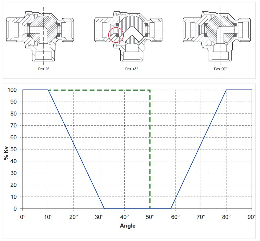
Fig. Characteristics of valve VBG6 (Source: Honeywell)
We must not forget to set the drive, if the drive allows it. The figure shows the default setting of the Honeywell MR6-024-010 actuator for the Honeywell VBG6 six-way valve.
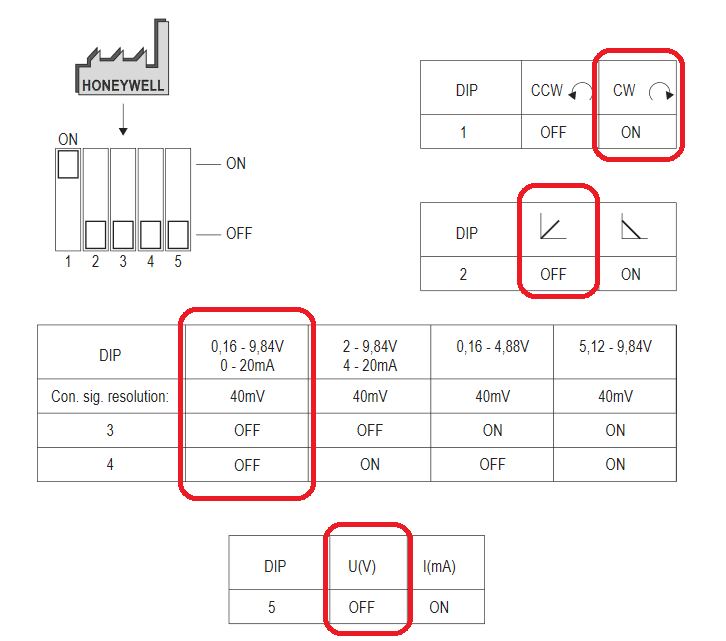
Fig. Honeywell MR6-024-010 drive settings (Source: Honeywell, highlight: author)
The default parameters are marked in red and in this setting they suit us, except for the direction of rotation. See figure with positions above: from 0° to 90°, the valve rotates counterclockwise. We have two options: either switch the direction of rotation on the drive (DIP1 = OFF), or set the parameters in FCR013 so that 10 V corresponds to 0°.
| point | angle | voltage for DIP1 = OFF | voltage for DIP1 = ON |
| H 100% | 80° | 8,88 V | 1,11 V |
| H 0% | 58° | 6,44 V | 3,55 V |
| C 0% | 32° | 3,55 V | 6,44 V |
| C 100% | 10° | 1,11 V | 8,88 V |
Tab.: Points for setting FCR013 for VBG6 with drive MR6-024-010
From a practical point of view, it will be more appropriate to leave the default settings of the switches on the drive and adjust the parameters in FCR013. When replacing the drive, there is no need to reset anything to the initial state, while when replacing the controller, the entire set of parameters is played anyway - setpoints, input logic settings, etc.
Concluding remark: with the exact beginnings and ends of the sequences, this will not be so critical, because the drives still have a certain hysteresis. That's why the deadband is so large, actually a third to a quarter of the working range of the drive. The main thing is that with zero energy demand, the drive is not in a position that represents a non-zero flow. This should fulfill the functions of transitioning to the center of the deadband. The precise control of the room temperature is finally ensured by the PI algorithm in FCR013, which, thanks to the feedback from the room temperature sensor, "tightens" the position so that the actual temperature corresponds exactly to the required one. Above all, we must make sure that the required direction of rotation is observed and verify during commissioning whether hot water actually flows into the register when heating is required and vice versa. We thus control the work not only of ourselves, but also of our suppliers of heating and cooling.
