MW240B for blinds control - part 1
Installation and recovery
When installing the blinds, the MW240-B module must first be configured using ModComTool:

Procedure:
- set the unique Modbus link address of the module (Address),
- in order to use the MW240B module for blind control purposes, this function must be enabled by setting bit 7 in reg 5 MSB (Allow function),
- next, measure (by reading from the blinds data sheet) the travel time from one extreme position to the other (Whole position time) and enter it in r. 19 LSB. If in your application you are working not only with full traversal but also with a run-up to the specific position, you will need to correct this value slightly at the end (see paragraph Final correction of the crossing time). This only applies to remote PLC control, not local control which is controlled by buttons,
- determine the specific movement time by pressing the button briefly (Move short time) r. 20 LSB, or how many angles of blade tilt will be achievable,
- finally, write the values to EEPROM (Write all to EEPROM) and reset the module,
- optionally it is possible to set what should happen in case of communication failure with the PLC (tab Relay action, Offline action).
For more information about the setting options, please refer to the Modbus table of the module.
Merbon IDE project
- create a new project,
- assign PLC,
- assign a channel (Modbus serial protocol),
- copy the new device from the sample project (MW240-B_sample) and copy as many devices as you have physically connected to the channel,
- change the device addresses as described in the previous paragraph (ModComTool),
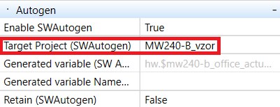
- all necessary variables are already pre-mapped in this created device library - select Target project (SWAutogen) in the data point properties,
- switch the assembly to Full mode and copy the function block MW420.FunctionBlock.st to your project,
- in the block properties select Include in compilation and Show in Explorer, after compiling the report you will find the block in the FUPLA blocks tab, from there you can normally drag it into your main.fbd program and work with it like with any other block.
Block inputs respond only to leading edges. They therefore expect short pulses to activate the individual command sequences. You create these short pulses by self-setting (astable flap circuit) the value of the variable, when activating the variable to log. 1, the block becomes unstable and after the delay time counts down, the value of the same variable is dropped to log. 0., see main.Program.fbd in the sample project.
To increase the reliability of the entire blind control system, it was necessary to sacrifice the reaction time from the activation of the sequence to the execution of the desired action. This time varies, depending on the total PLC load (program loop time). Each sequence consists of at least parts Stop + requested command + ModbusEnable + release.
The inputs of individual blocks can be connected to each other and thus create individual groups that will respond to individual commands identically (eg Wind = all up).
There is always only one output from the block, which is fed to a variable, which is mapped to the control register (line 17) of the MW240-B module.
Common errors: If the project cannot be compiled, Autogen may be set incorrectly. This happens when copying device libraries between projects. To repair, reopen the MW240-B on the Modbus channel and select the correct target project (SWAutogen) in the data point properties.

Final correction of the crossing time
After reactivating all modules, we will briefly test the setting of the correct crossing time:
- when debugging the project in the PLC, manually send a command to go up (or a calibration command),
- wait until the blinds move to the upper position and at the same time check that the current position r.16 LSB is 0 %,
- now run the command to move the blinds to the lower position (r.17 MSB = 99 %), observe the blinds, and at the same time read the current position (r.16 LSB) - this is updated approximately every 3 s (depending on the PLC load), at the moment of stopping the blinds in the lower position write down the value of the current position (r.16 LSB) (value when reaching the lower position) - it will probably be less than 99,
- correct the value of the crossing time (Whole position time) r. 19 LSB experimentally or according to the formula:

- enter the value New crossing time in Whole position time (r. 19 LSB).
The calibration is done. To be sure, you can perform the test, this time from the lower position to the upper. At this point, the blinds in the upper position should stop at approximately the time when the current position (register 16 LSB) is 1 %.
This recalibration should be performed for each window (or blind drive) separately.
