Unlike other combined I/O modules, the MW240-B module is equipped with a separate micrologic that controls both outputs depending on the inputs or entries in the Modbus registers (used for lighting control) or enables the control of one group of blinds. If the module is configured for lighting control, it is possible to set the so-called button (edge response) or switch (state response) logic. The following explanation applies to the MW240-B. Setting the function of the buttons makes it possible to use priority to solve even systems where it is not possible to programmatically control the writing of the PLC on the Modbus bus, i.e. telegrams are sent periodically from the PLC and it is not possible to send the required settings only when the state changes.
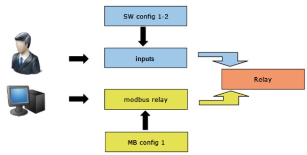
The MW240-B module switches relays according to user button presses or Modbus commands. Priorities and sense of control can be set using configuration registers. In this way, the module can be set for the desired function - local control, conversion by bus control, combined control ("the last entry applies"), etc.
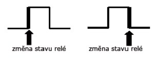
On an incoming edge, the state of the relay changes. It reacts to a rising or falling edge.
| Registry | Value |
| SW config 1 | 0x05 |
| SW config 2 | 0x00 |
Copies the state of the input to the output, but is written to the Relay register only when the state of the input changes.
| Registry | Value |
| SW config 1 | 0x50 |
| SW config 2 | 0x00 |
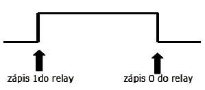
Constantly (in the cycle of executing the microprogram in the module) it copies the state of the input to the output.
| Registry | Value |
| SW config 1 | 0x00 |
| SW config 2 | 0x05 |
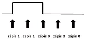
The state from the Modbus relay register is constantly (at the time of execution of the microprogram in the module) copied to the Relay.
| Registry | Value |
| MB config 1 | 0x05 |
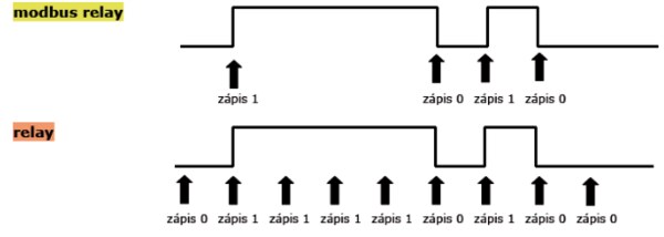
When the value of the Modbus relay register is changed, the new status is copied to the Relay.
| Registry | Value |
| MB config 1 | 0x0A |

For any write to the Modbus relay register, its status is copied to Relay.
| Registry | Value |
| MB config 1 | 0x0F |
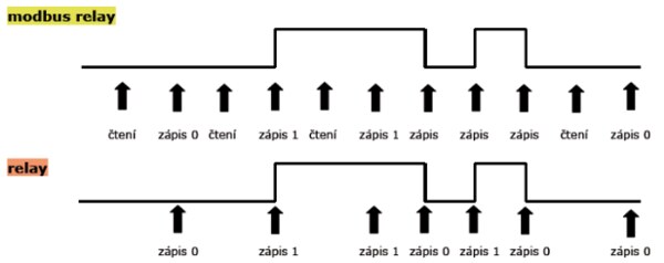
If the Button Copy function is selected at the same time as the Modbus Status function, the priority
is selected in the SW/MB config 1 register (6 LSB register).
Both signal sources (buttons and entries via Modbus) can be combined. The function of the outputs looks accordingly.
Inputs function: Edge (rising), Modbus function: Modbus change.
One-time write Off on the bus when leaving the zone goes out ("drops") all lights including those left on by mistake. If someone in the zone were to press a button, the corresponding light would turn on.
Inputs function: State change, Modbus function: Write via Modbus.
Periodic write Off on bus during the time the building is empty, prevents manual power on using the power switch. Even if someone in the building changed the state of the switch (i.e. turned it off and on), the corresponding light would remain off, the periodic write overwrites the one-time event from the switch. When the building is reoccupied, the periodic recording is terminated and thus control is again passed to the input logic.
Input function: Copy buttons, Modbus function: Modbus status.
When the central light is turned on for cleaning, the priority in the SW/MB config 1 register is set to writing via Modbus has priority. After Modbus, the signal to turn on is written. All the lights come on. After the cleaning is finished, the priority is set back to control according to the inputs and the lights return to the state before the cleaning.
Inputs function: Button copying, Modbus function: Modbus status.
In case of strong wind, the priority in the SW/MB config 1 register is set that writing after Modbus has priority. A signal to pull out the blinds is periodically written via Modbus, the buttons are thereby disabled and the blinds cannot be pulled down manually. After the wind subsides, the priority is set back to input control with a delay, and the blinds can be operated manually again.