In the first part, we got acquainted with various ways to transmit serial data over Ethernet and showed the basic connection and configuration of Modbus RTU / Modbus TCP router. Now let's look at some less common topologies.
Sometimes we need the opposite connection: we have a Modbus TCP server, for example an air handling unit (typically a VTS brand with a Carel controller equipped with a TCP / IP expansion module) or a network analyzer (eg Siemens Sentron), and we need to read data from it into a client - this is for example a PLC which only talks Modbus RTU. This also includes situations where it was not possible to route an Ethernet cable between the Modbus server and the PLC, either because of a distance exceeding 100 m or for a complicated situation on the construction site. Some routers can also use this upside down connection, topology of which is shown in the figure to the right.

Fig. 7: Modbus routing topology – 1.
In this case, it is necessary to realize one important thing: The Modbus TCP query also includes the IP address of the target device - of the server. However, the Modbus RTU client does not have any means to specify it: the Modbus RTU protocol can not do such a thing, it does not know of the existence of a network environment at all. This information must be supplied to the router by setting up the routing table in the router. For Domat R035, the table is configured via its web interface. To get started, set the converter to Industrial Automation mode and select Serial Master as the active protocol:

Fig. 8: Setting the converter as Serial Master
The Slave destinations (Packet Routing) item appears in the serial port configuration menu.
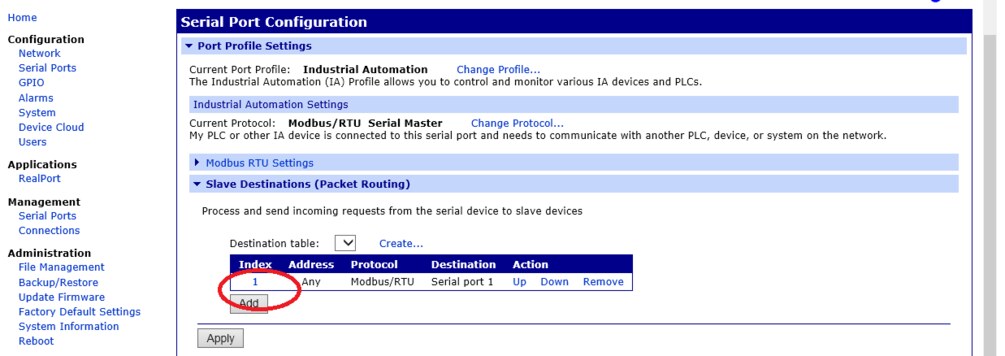
Fig. 9: Converter R035, menu with routing table
By clicking on the number in the Index column we get to the settings of a particular routing rule.
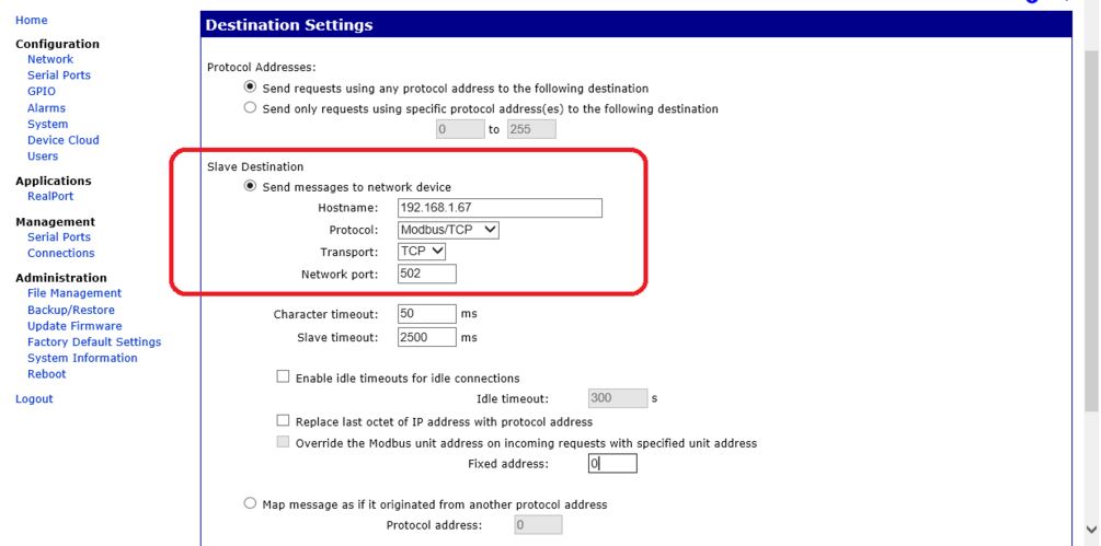
Fig. 10: Setting the routing rule in R035
In this case, all requests ("Send requests using any protocol address…") received by the converter on the serial port will be sent to the IP address 192.168.1.67. Protocol address here means the serial address of a serial device, i.e. the "classic" Modbus address in the range of 1 to 255. If we have a topology with a single Modbus TCP server (as shown in topology 1 on the right), this setting should be enough.
How to work with line addresses in Modbus TCP query? The standard is that in Modbus TCP queries, the address is set to 1. The Modbus TCP server itself should not address the Modbus link addresses at all, it should respond to all addresses in the same way, and always return the address from the query in its response. (Exceptionally, the Modbus TCP server uses line addresses as a kind of write protection - for example, for Solaron photovoltaic inverters, the telegram for setting power limitation must have a line address of 0, although the standard address of 1 is used to read the same register as well as the others.)
Moreover, if there is no Modbus IP server behind the IP address, but a router and the entire Modbus RTU bus that already needs line addresses for communication, the situation becomes complicated. In practice, we prefer to avoid this topology, but sometimes a similar setup can help us to get out of a tight spot.
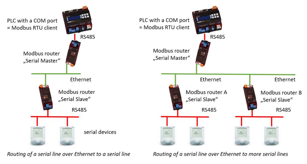
Fig. 11: Topology for Modbus routing – 2.
In the picture of topology 2 on the left there is a simpler case when we just need to create one routing table, actually the same as in the case of topology 1 on the right. The router configured as Serial Master follows the "Send requests using any protocol address to the following destination" rule and sends queries with all link addresses to the router with the Serial Slave configuration.
It routes them to the serial link and sends the responses from the serial devices over the network as Modbus TCP telegrams back to the router with the Serial Master configuration. For routing to multiple serial lines, as in the topology 2 on the right, we need to create more tables in the Serial Master router to route the telegrams to router A or router B, depending on the line addresses of the devices behind the routers. Note that the serial client (here PLC above) cannot reach more than 255 devices, which is the maximum logical number of addresses on a single serial line. (For the link adress, as can be seen in the disassembled telegram above, there is one byte reserved in the packet. The address then can be 0...255.) How to address serial devices on individual lines? As an example, take two buses, each containing thirty Modbus RTU devices. This means that the total number of devices behind all Serial Slave routers must not exceed 255, even if each of the routers would be able to serve up to 255 devices individually.
How to address the serial devices on individual lines? As an example, take two buses, each containing thirty Modbus RTU devices.
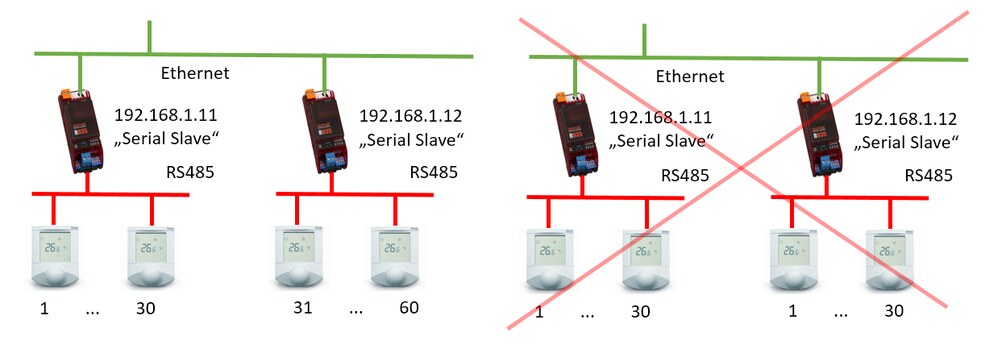
Fig. 12: Addressing on serial lines when routing a serial link over Ethernet to multiple serial lines
In the picture on the left, the links are correctly addressed so that there is no collision of addresses. We need to create two tables in the Serial Master router, each of which forwards the telegrams to the Serial Slave router, followed by a device with the appropriate link address. An example of a table in the Serial Master router is here:

Fig. 13: A routing table that forwards queries to line addresses 31 through 60 to IP address of 192.168.1.12
In the Serial Slave router with IP address 192.168.1.12 then we have to specify that only serial address queries 31 to 60 are sent to the serial line. If we let the whole range of addresses be forwarded from 0 to 255, the router would returning error messages on queries to addresses which do not exist at its serial line. This would then (at the application level) conflict with valid responses from the other router. The correct setting in the Serial Slave is shown in the following figure.

Fig. 14: Serial Slave router settings for line addresses 31 to 60
Addressing with duplicate line address ranges is only possible when the master is communicating via Modbus TCP, as shown in the section “Routing Modbus RTU to Modbus TCP”.
Unlike a serial (Modbus RTU) line with only one master at a time, in the case of a Modbus TCP network, it is theoretically no problem for multiple clients to connect to one server and each read and write data to the Modbus TCP server independently. It only depends on how many clients (or Modbus TCP connection) the Modbus TCP server can host at a time. Simpler converters can handle only one Modbus TCP connection, more powerful ones 3 to 4 client connections at a time. Specific options can be obtained from the manufacturer.
Queries to the router seem to come from clients "in parallel", but actually they are serialized on the Ethernet. They are queued, sent to the serial line and handled one after another. The topology looks like this:
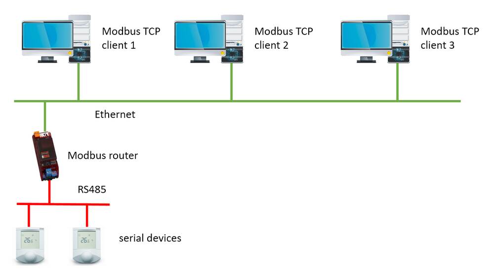
Fig. 15: Multiple Modbus TCP clients over one Modbus TCP server
Therefore, the advantage of routing Modbus RTU to Modbus TCP is the possibility of using more clients, i.e. reading data from one serial bus into two or more different systems. This is not possible on the serial line itself - if more masters are connected, there would be collisions on the line that Modbus RTU cannot handle. In practice, collisions would result in communication outages (timeouts) on all masters.
It would be possible to construct more topologies, such as multiple Modbus TCP servers under one Modbus RTU client, a combination of Modbus TCP servers and Serial Slave routers under multiple Modbus RTUs and TCP clients, etc., and so on. However, if we are not dealing with an exceptional situation or supplementing an existing system, it is good to avoid more complex topologies. The less configurable devices in the system, the easier service and maintenance. When readdressing the network, which is not such an exceptional event, it is necessary to revise and reconfigure the system.
With more complex settings, it is more than advisable to back up the entire R035 configuration using its Backup / Restore menu. The backup file will help to quickly recover if the converter is replaced or will serve as a quick aid for configuring other converters to have the same function.
In case of a topology with a converter in the Serial Master mode, it should be noted that the serial device in the master function may need to check and possibly increase the timeout - the maximum waiting time for a response. When routing and transmitting Modbus packets over the network, there is a delay that the master could evaluate as a communication error. When operating in a local network, a timeout of about 300 ms should be sufficient; in case of troubles a Wireshark dump can help a lot.
Remember that the Ethernet is a data highway compared to a serial line. Therefore, there should be gaps between Modbus TCP client queries (in range of hundreds of milliseconds) so that the serial line can process the data. This is especially important if multiple clients access a single Modbus TCP server at the same time.
Another risk may be reduced network security. Modbus TCP has no security, password protection, etc., it is simply a table exposed to an IP address and can be read and written by any client in general. Therefore, when routing, we have to pay attention to the networks in which we operate. In a separated technology network, there are usually no problems. However, when transmitting over a corporate network or even over the Internet, it is necessary to separate the part where the Modbus devices are located by using a virtual private network, or to protect against unauthorized reading and writing in another way.