When integrating devices with the Modbus protocol, we cannot avoid reading and writing analog values. However, unlike some other protocols, Modbus does not define analog value formats in its standard. Its registers carry 16-bit numbers that can be interpreted in several ways. Supplier of integrated equipment (Modbus server), resp. its Modbus tables, it must therefore provide documentation from which it will be clear how the read data is to be converted to a number that corresponds to the relevant quantity. Unfortunately, sometimes this documentation is not complete or understandable, and then it is necessary to experiment a bit. In the following somewhat longer, but I believe that the more interesting text will show how to proceed in practice when putting the equipment into operation.
Suppose that the communication itself is already revived and the device returns some data. It is important whether the analog value is transmitted via one register ("fits" up to 16 bits) or whether it occupies more registers: two or four, ie 32 or even 64 bits long.
In the Modbus table, we know this mainly by the register numbers. If they follow each other without spaces, these are 16-bit values: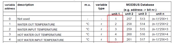
Uniflair Modbus table, register numbers for the respective indoor unit are in the "unit X" columns
For 16-bit values, it is also necessary to find out how the decimal numbers are represented. The 16-bit word is generally able to take the values 0 ... 65535. For the transfer of physical quantities, such as temperature, it is more appropriate to choose a format that allows the representation of negative values - ie integer (signed). It then has a range of -32768 to 32767. In order to obtain a higher resolution, to one to two decimal places, the value is multiplied by 10 or 100 on the server before being written to the modbus table. This format is then called HVAC integer. Therefore, if we read from the register with the room temperature, for example, the value 2230, after dividing by the constant 100, we obtain a temperature of 22.3°C. Constant and physical unit information must be given in the modbus table.
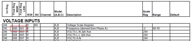
For example, Vacon frequency converters have a constant for each variable listed separately in the right column of the table, Scale - see figure. The value read from the register (the register number is marked here ID) is therefore multiplied by the appropriate constant, ideally in the input transformation, if the programming environment allows it.
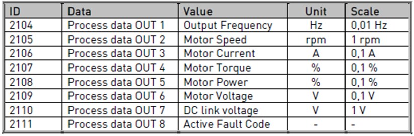 Cutout from FM Vacon modbus table
Sometimes the constant depends on the type of device. The types differ, for example, in performance, and the scaling is chosen for each type so that the highest possible resolution is achieved and at the same time the range does not overflow. Then we have to look in catalog sheets or other documents:
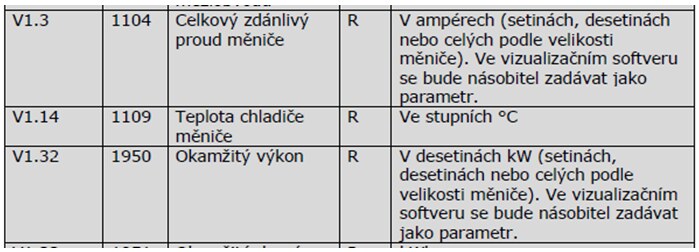 Cutout from the Modbus table of Vacon PV inverters
Pay attention to the type of variable in the application program. You must select an unsigned or unsigned type, depending on what the format looks like on the Modbus server. We encountered an error where the outdoor temperature was transmitted over the bus and the relevant variable was declared as an unsigned integer in the client program. The scaling (in this case division by 100) was fine, everything worked until the outside temperature dropped below freezing. At that moment, the variable on the client's side "undercut" and gained values over 650°C, which resulted in the shutdown of the heating system.
The constant does not always have to be just a "round" number:
 Cutout from the Buderus Modbus table, interface for the Ecobus bus
In this case, for example, we would have to enter the value 43 (decimal) to set the desired temperature of 21.5°C.
Transformations can sometimes take on absurd forms, some air conditioning units require conversion of the measured or set temperature according to a nonlinear table with 20-30 points. Such a situation is already ripe for writing a special transformation function or modifying a client program; by conventional means, such as the linear transformation y = kx + q, we would not achieve the required accuracy.
Somewhere the range of the 16-bit variable is not enough, for example if we want to (with the necessary resolution) transmit the energy measured by the electricity meter. These are usually cumulative values - energy, but due to standardization, especially with electricity meters, we often encounter 32-bit values for quantities such as voltages and currents. Modbus server authors then use two consecutive registers to transfer one variable, thus gaining 32-bit space. DINT (double integer) or UDINT (unsigned double integer) types are used for 32-bit integer values in application programs according to IEC 61131.
Thirty-two-bit values can be recognized by three characters:
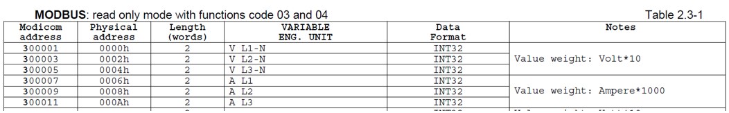
In the picture below we see that, for example, the Modbus table of the EM23-DIN electricity meter contains all three data. Modicon address is the numbering of registers from 1 with the notation 3xxxx, Physical address is the same series, but in hexadecimal format and starting from zero.
 Modbus table of the Carlo Gavazzi EM23-DIN electricity meter
In the ModComTool Modbus client, the read values look like this:
 EM23-DIN values read by ModComTool
The voltage values must be divided by 10, as explained in the last column of the Modbus table. At first glance, we see that the phase voltage is approximately 237 volts.
If our application software allows only sixteen-bit values to be processed from Modbus, all you have to do is take the upper word (MSW), multiply it by 65536 and add the lower word (LSW) to it. The result is usually a value of type real, which can mean
Pay attention to the word order. The manufacturer of the electricity meter, Carlo Gavazzi EM23-DIN, also states in the documentation that the register (word) with a lower weight (LSW) comes first on the bus:![]() Therefore, it is necessary to specify the correct order of incoming data in the variable definition:
Therefore, it is necessary to specify the correct order of incoming data in the variable definition:
 Setting of variable type INT32 for electricity meter EM23-DIN
Thus, after receiving, the words are sorted so that the first received one (bytes 12) is taken as LSW (least significant word), and the second (bytes 34) as MSW (most significant word). Client programs can usually set this order, either in the form of switches with the names "Hi-Lo", "Reverse byte / word order", "Word rotate", etc., or by specifying the byte order next to the variable definition. This is the case, for example, with the Merbon IDE, as we can see in the picture above.
The IEEE 754 standard defines, among other things, the representation of floating point values for 32-bit and 64-bit formats. For basic precision, 32 bits, the bit space distribution is as follows:
Exponent and mantissa are even coded, but we may not be interested. It is important that the read data must enter the calculation in the correct order of words and bytes. How to achieve this on Modbus, which works with 16-bit registers?
As with long integers, for a 32-bit number, one value takes two 16-bit registers. The problem is that the sorting of registers (and sometimes bytes in the registry) may not be clearly described in the documentation. If the client program fails to follow the same ordering of bytes and registers as on the server, the read value is invalid at best (it does not follow the prescribed format), which is obvious at first glance, meaningless at worst. Although the Modbus table sometimes describes the correct order, the question is whether the client program uses the same terminology. Usually, the fastest reading solution is just to try.
In the following table, three temperatures are transmitted as 32-bit real variables. So each occupies two modbus registers:
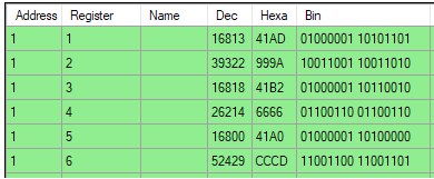 Three 32-bit real values
Communication via Modbus TCP in hexadecimal format for reading registers 1 and 2 looks like this:
query:   05 6D 00 00 00 06 01 03 00 00 00 02
answer: 05 6D 00 00 00 07 01 03 04 41 AD 99 9A
The contents of both read registers are shown in bold. We see that in the telegram the lower register (containing the value 41 AD, in the green table with the number 1) comes first and the bytes are compared in the order higher - lower. The byte order in the Merbon IDE must match this:
 Specifying the byte order of a variable in the Merbon IDE
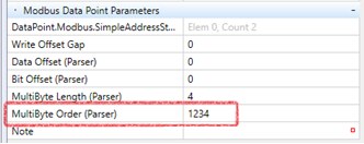
The above standard order "first comes the register with the lower number that contains the more significant word, each register has its higher byte first" corresponds to the string "1234". It says that in the same order in which the data arrives on the bus, the variables of the float data type are stored in memory.
Another example is reading the temperature from the Papago 2PT_ETH module (5 registers are read at once in the query, we are interested in the 3rd and 4th in order):
query:   05 53 00 00 00 06 01 04 00 6E 00 05
answer: 05 53 00 00 00 0D 01 04 0A 00 00 00 F6 41 C5 21 52 00 00
The two registers, representing the temperature at inlet 2, are marked in bold. As in the previous case, in the lower register (comes first) there is a more significant word (41 C5), in the higher register there is a less significant word (21 52). The measured value is 24.641 ° C. We can calculate it for checking with one of the internet calculators or an IEEE 754 value conversion program. The order is therefore standard, there is no need to change anything and the Multibyte Order would again be "1234".
Likewise, the registers have a PowerLogic BCPM current meter, which states in the document describing the Modbus table:
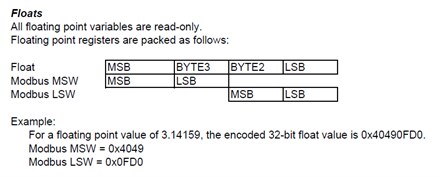 PowerLogic BCPM – Float value format description
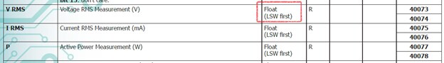
The table itself shows the register numbers for MSW and LSW:
 PowerLogic BCPM – cutout of modbus table
MSW is in the lower registry, it will come first, so even here the Multibyte Order would be "1234".
Sometimes the manufacturer just specifies the order of the registers (words) in the note:
 Modbus table of the QI-POWER-485, QEED / DEM electricity meter probe
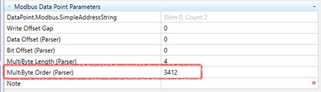
Here, however, the word with the lower weight (LSW) comes first, so the Multibyte Order is "3412" - the words must be stored in the reverse order. The byte order within the word is retained.
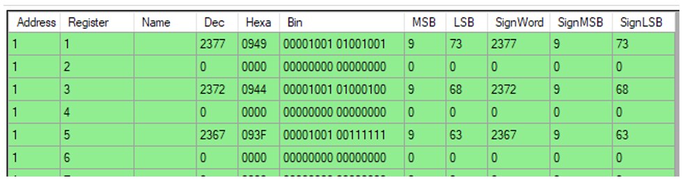
When entering the initial register of the variable, we must pay attention to whether the server uses numbering from 0 or from 1. If there are consecutive numerically similar values, such as several room temperatures or voltages for the three phases of the meter, a mistake may occur. The correct grouping into 32-bit variables is shown in the following figure on the left. If we accidentally read a variable of type real from registers 2 and 3, as in the picture on the right, and at the same time the word order was reversed (ie MultiByte order would be 3412), the number read will be 22.325, which may give the impression that it is by a valid value. But this is a wrong consideration, then the whole communication would not work properly.
 Left: correct shift, right: wrong shift
The problem is similar for 64-bit registers, the default order of multibytes is "12345678", so the lower registers come first, in each register there is a more significant byte first. We process the values with a variable of type lreal (long real), which represents a 64-bit floating point number.
Some manufacturers, such as Gossen-Metrawatt, have chosen their own - non-standard - floating-point value format for their instruments. The following description can be found in the documentation for the U228X electricity meter:
 Gossen-Metrawatt U228X, description of the format of instantaneous values
In one 16-bit register the base (mantissa) is as a signed integer and in the other it is in the same exponent format. In this case, probably the Modbus client (SCADA or programming environment for PLC) will not have such a predefined transformation and we must get to the result by reading each value separately and their subsequent processing in the application program according to the above example from the documentation.
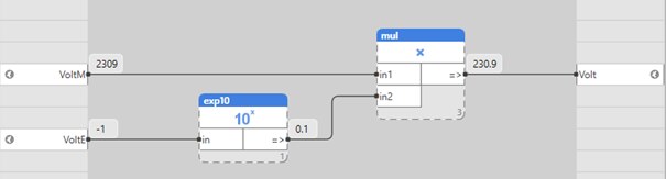 Value processing from two registers in Gossen-Metrawatt "type 1 format"
You can't rely on the exponent not to change and simplify your work by simply dividing the value from the first register by ten. This procedure would be a gamble, which could be a mistake even after several years of trouble-free operation, in a situation where we expect the least.
If we read a few dozen similar values, it is definitely worth writing your own transformation in the form of a function block or better an ST function, if the development environment allows it. The value could then be read as one 32-bit variable, contained in two registers. This variable would not make sense in itself and would have to undergo a transformation:
Toshiba has solved it even more complicatedly with its older TCB-IFMB640TLE communication interface. It uses a 16-bit float format, which we probably won't really find in transformations in development environments. Unlike the IEEE 754 standard half-precision binary floating-point format, which has 5 bits reserved for the exponent, there are four bits for the exponent:
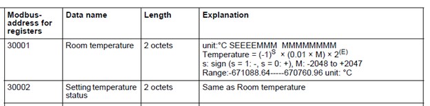 Toshiba, implementation of 16bit Float in TCB-IFMB640TLE
In this case, it would be necessary to either write your own function in structured text or another scripting language, or parse the contents of the register into individual bits and then calculate the mantissa and exponent and complicate the resulting temperature.
This example shows how important it is to examine analog value formats in the design phase and not be satisfied with the assurance that the device "communicates via Modbus", because this problem can mean at least more work for the application programmer, or worse, an insurmountable obstacle in commissioning of the equipment.
