The aim of the electrical energy distributor is to keep the consumption curve in time as flat as possible. One of the measures to achieve this is to prevent load peaks at individual customers. In terms of contract, it means that the customer must not exceed the maximum amount of electrical energy contracted during a 15 minutes time span. This amount of energy is called a „15-minutes maximum“. If this limit is exceeded, the customer pays a penalty. Achieving and exceeding of the limit is monitored by a digital energy meter installed at the customers‘ premises. The bigger the contracted value, the less risky the plant operation is, but customer pays higher flat fees for higher reserved consumption limit.
In order to use the contracted value efficiently, and avoid paying penalties at the same time, customers use load shedding controllers. The controllers are monitoring the current consumption, and if there is a risk of exceeding the contracted limit, they switch off selected appliances automatically. If the appliances are grouped properly, the originally contracted limit value can be decreased, which brings savings on the flat fees. The load shedding controller may then pay back in a short period; of course it depends on how much power can be switched off at any time without risking operation problems, and on allocation of the appliances into groups.
As input information for the controller, we need the amount of energy consumed in the current 15 minutes interval, and information on when the current interval starts and ends (the controller must be synchronized with the energy meter so that it calculates the same data: the interval must start at the same time as the reference interval in the energy meter).
The amount of energy consumed is read as pulses from the pulse output of the meter. The energy distributors tend to have strict rules regarding devices that are allowed to connect to the meter, and they require optical signal separation in order to protect the meter’s outputs. The optical separators are usually supplied by the electrical installer who installs the meter, because the meter terminals are sealed. The output for the load shedding controller is most frequently an open collector output which connects to the counting module input (e.g. Domat M710), while each pulse represents a certain amount of energy consumed. The counting module counts pulses during the interval, and provides the cumulated energy data. Another option is a S0 output, which is a reed contact or open collector completed by resistors so that in the active state the output impedance is lower than in the inactive state. This kind of output used to be installed mainly because there is no risk of sparks here. Another pro is that a broken cable can be detected (which gives infinite impedance rather than impedance changes).
The second signal is the synchronisation pulse. From the electrical point of view, it is the same as the energy amount signal. It is sent by the meter every 15 minutes, with start of every measuring period. Based on the rising edge of the sync pulse, the load shedding controller starts a new measuring period.
The controllers use one algorithm or a combination of more strategies. At more sophisticated controllers, uses can set up the required strategy type, as well as weight which will be assigned to each strategy, or the strategy weight may even change in the course of the interval. The appliances are grouped according to priorities. There are 4 to 8 groups usually, and each group has different switch-off and switch-on parameters.
The point is that after a defined amount of energy has been consumed in the interval, a group is thrown off. Based on analysis of average consumption chart, a safety area must be defined at the start of the interval, where the algorithm is not active and all groups are switched on. The level strategy is also used by most of the controllers as a safety measure which switches off all groups immediately after the contracted limit has been exceeded.
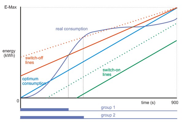
This is the most frequently used strategy. The ideal consumption line connects the starting and ending points of the interval with consumptions of 0 and E-Max (the contracted maximum). If the real consumption goes above any of the switch-off lines, the respective group is thrown off. If the real consumption happens to return under the switch-on line by the end of the interval, the group is switched on again. For the sake of clarity, there are only two groups in the chart, with lines full and dotted. Group 1 (full line) has lower priority, i.e. it contains not so important appliances, and is the first to be thrown off. Group 2 (dotted line) is thrown off at a later stage, the controller tries to keep it up as long as possible, and, eventually, switch it back again as soon as possible.![Compensation strategy (according to [1])](https://domat.blob.core.windows.net/imagehandler/domat.blob.core.windows.net/cms/ContentItems/348_00348/giUXgt/m_max__w_600__h_2000__o/kompenzacni-1-en.jpeg)
Compensation strategy (according to [1])
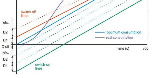
There are controllers with up to 8 or more groups on the market, rather than the two groups plotted in the chart. Some of the controllers use the switch-on lines parallel to the ideal consumption curve; there are rather high differences used in the chart below, so that even if the consumed power has been decreased, none of the groups is switched on again in the current period. To achieve that, the real consumption curve would have to cross one or more switch-on lines.
Compensation strategy with parallel switch-on lines
At the prediction strategy, the crucial information is the consumption trend, or momentary consumed power value based on the interval time. The total energy consumed is predicted based on assumption that the current power will not change until the end of the interval. If the E-Max (maximum contracted) value would be exceeded by the end of the interval, the group is thrown off (red lines – their tangent is higher than the tangent of the line connecting the current point with the [15 min., E-Max] point, and thus the lines cross the E-Max value before the end of the interval is reached). If the controller would predict lower consumption than E-Max to the end of the interval, the group is activated again (green lines – they cross the E-Max level only after the end of the interval).![Prediction strategy (according to [1])](https://domat.blob.core.windows.net/imagehandler/domat.blob.core.windows.net/cms/ContentItems/348_00348/So7iKP/m_max__w_600__h_2000__o/predikcni-en.jpeg) Prediction strategy (according to [1])
Prediction strategy (according to [1])
The load shedding controller may well be a separate hardware device, but if there is a Building Management System (BMS) installed on the premises the strategy may be programmed in the BMS controllers. The advantage is easy integration into SCADA including trend data, but the main benefit is that the load shedding can actuate all BMS-controlled appliances and aggregates, even in different panels: the control signals are transferred over the BMS communication bus. This means that there may be aggregates from different parts of the building in a common group, as there are no extra costs for the communication between the panels.
When engineering in RcWare SoftPLC IDE using the T34 load shedding block, there are questions on how the input values relating to energy shall be calculated. The block uses compensation strategy with parallel switch-on lines, and controls up to 8 groups of appliances.
It is quite clear with Ein (kWh). This is the amout of consumed energy, an increasing value from 0 to the value cumulated in the 15th minute of the interval. (The Ein value is reset to zero automatically in the M710 input module on the rising edge of the sync pulse from the meter.) The number of pulses must then be multiplied by the weight of a pulse, or in other words, by the value which tells how many kWh a single pulse represents.
Tin (s) is the current time of the period, usually 0..900 s; this value is generated in the M710 module, and is automatically reset on the sync pulse, too.
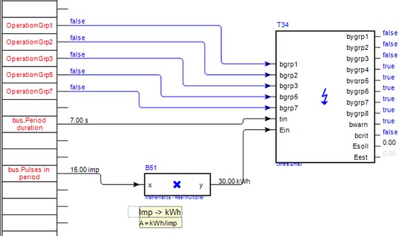
Simplified usage of the T34 block
The Emax parameter is described in the help as „maximum energy in the measured period“. The period is the 15 minutes interval. As we talk about energy (or electrical work spent), we use kWh. The snag is that this is energy consumed during fifteen minutes, while the „h“ in „kWh“ reminds a hour. (If we used another energy unit, such as megajoule (MJ), this confusion would be gone.) That is why engineers sometimes tend to multiply this value by four („because a hour is composed of four 15-minutes intervals“). This is basically wrong, it still is the amount of energy consumed by the building during 15 minutes, i.e. in one measuring period. If you do not agree now, please hold on, it will brighten up in the next paragraphs.
The E-Max parameter is entered based on the data from the energy distributor: the contracted 15 minutes maximum. The operators, however, call it
contracted 15-minutes power. Physically, it is suspicious – power is rather an instant than a cummulated value! It is a value of power which, if constantly consumed over 15 minutes, would provide the same amount of energy as the contracted 15-minutes maximum. In other words, it is the average power allowed over the 15-minute interval.
To get the Emax parameter, the contracted 15-minutes power must be divided by 4.
All the other parameters (Esoll, Eest) are in kWh to the current 15-minutes period.
To optimize the load shedding, the switch-off differences have to be set: parameters D1 to D8 which should reflect the power consumption of the groups. Again, it must be noted that numerically we need the 15-minutes energy consumptions. If a group has aggregates of 80 kW in total, it consumes 80 kWh in a hour, and 80 / 4 = 20 kWh in 15 minutes. The respective parameter is 20 (kWh). The D off is hysteresis, or offset of the switch-on lines against the (blue) line of ideal consumption. Switch-on and switch-off differences
If we want the E-Max value to match numerically the contracted 15-minutes power, the parameters would have to be multiplied by the number of 15-minute intervals in a hour, which is 4. The E-Max would then be set to (according to the example above) 600 (kW), current consumption would enter the T34 block as Ein*4 (kW), unit cross-check: kWh/(h/4), or kilowatthours in a quarter of an hour. „Consumption“ in kW makes no sense indeed, but numerically, it is OK. The value could be also called „average power in the current 15-minutes interval“. In a similar way, parameters D… should be corrected, which then would have values of group power in kW. This way of presentation is more frequent and easier to understand for the users than the real values which are numerically four times lower.
The T34 block offers this setting so as to be more versatile: note that it is possible to change the interval length which does not have to be 15 minutes only. The block can be utilized for limitation of consumption or production of any kind of energy or media (water, gas etc).
To achieve as fluent energy consumption as possible without any constraints on building operation, the load shedding follows in more groups with different priorities. The lowest priority is switched off first, the lowest priority as the last one. Available load shedding controllers usually control 6 to 8 groups. It is apparent that the less important aggregates or appliances with accumulation are cut off first, like domestic hot water tank, or electric boiler. After them, more important technologies follow: it is possible to limit operation of large air handling units (unless they supply a sensitive technology) or chillers for air conditioning. Critical appliances, as illumination or commercial cooling, is mostly not allowed to be switched off. Assignment of appliances to priority groups must always be approved by the building operator who must be aware of the consequences of load shedding on the building technologies. At more complex buildings, it is possible that the building operator himself is able to assign (using SCADA) the aggregates or groups of aggregates into priority groups.
The assignment into groups is always a discussed issue. We also have to be aware of the fact that frequent switching reduces the lifespan of motors, and there are aggregates which must not be switched on immediately after they have been thrown off. A minimum switch-off time has to be kept.
Note that the main consumers of energy, commercial cooling compressors and sales area lighting, must not be switched off for technological and safety reasons.
As the groups are thrown off, it may be that the group to be switched off is not active for operational reasons, e.g. the electric boiler heating is off because the water has reached its setpoint temperature. It is clear that switching off this group does not help much to reduce the consumption; the appliance is not active anyway, and the controller is only losing time to learn that the undesirable trend is going on and to switch the next group in line. That is why we use, wherever possible, the operation feedback signal. If a group is not active, it is skipped automatically, and the next group with higher priority is switched off instead.
To indicate operation, there are binary inputs in the T34 block. At the screenshot below, there are signals from groups 1, 2, 3, 5, and 7. Groups 4, 6, and 8 were not able to provide the signal – either it is not available in the system, or a group controls several devices with low power. These groups have their feedback inputs hidden in the block, and are switched off „blindly“ so as if they are operating. The controller simply expects the shedding of a group to reduce the consumption.
Group operation feedback signals
Similar problem may appear also at energy production facilities: photovoltaic plants are not allowed to bring more power into the grid than the allowed maximum.
The BMS supplier should specify in the requirements to the other suppliers that the customer, or rather his electrical installation supplier, provides the optical separators and their installation with the energy meter. The connection is sealed and only subjects authorised by energy distributors are allowed to do this. It is advised to remember to organize the installation until the installers leave the site definitely.
It should be as short as possible to avoid interferences and induction of false pulses which may result in switching off groups when unnecessary. Try to install the counting module as close to the meter as possible. However, the meter tends to reside in the high voltage distribution room which is not accessible to everybody. If a length of 10 to 15 m is not exceeded, there should be no major problems.
This value should be noted on the meter label. It is better if the pulse weight is confirmed by the energy distributor. The figure may be irrational, so e.g. at 3 imp./kWh it is good to use maximum resolution when entering the pulse weight (0.3333333 kWh/imp.).
The transformer ratio must be considered when calculating the pulse weight. It is advised to measure the energy consumption within a certain time using pulses, and check with the meter reading on the display. Both values must match, of course.
It is approved by the customer, as the prioritization of appliances will affect the performance of the building. The problem is that sometimes there is hardly anything to control, as there are no relevant aggregates that could be switched off, or the aggregates are difficult to control (they are in distant panels etc.). In this case, the contracted E-Max value must be increased.
The correct E-Max value given by the contracted power, reduced by a safety margin, must be set, as well as the switch-off differences according to designed or measured consumptions of the grouped aggregates. It is necessary to monitor the consumptions and switching of the groups on a long-term basis, and analyse if especially the switch-off differences are set correctly.
The energy manager should, after sound consideration, contract a suitable value of E-Max so as to minimize the overshoot risk and to pay the lowest possible flat price at the same time. There are also seasonal influences – if there is a danger of E-Max overshoot only several times a year and the rest of the year the consumption is deeply below the E-Max, it may be cheaper to pay the penalties from the savings brought by the lower contracted E-Max threshold. If the consumptions are more balanced, it is better not to run the risk. To select a suitable strategy, it is good to analyse the trend data and put together detailed information on the nature of the consumption. If there are aggregates with unbalanced consumption in the technologies, suppressing of parallel operation and distribution of the operation cycles in time may also help.
[1] http://www.lubosprokes.cz/maximum.php