For Modbus input modules, we sometimes have trouble reading short input signals, such as pressing a button or a signal from a presence sensor. The latching function in the input modules allows to read even short pulses that could be overlooked during sampling. In the following text we will show how it is implemented in I/O modules and especially how to use it when reading inputs in a program in a PLC.
In the module, the inputs are read either by interruption or - more often - within the main program loop, which reads the inputs with a frequency of the order of 10 Hz. The input pulse should therefore have a length of at least 100 ms, which is usually not a problem to guarantee. (Counter inputs that process an input signal of up to 50 Hz can be used to detect pulses with even shorter lengths.)
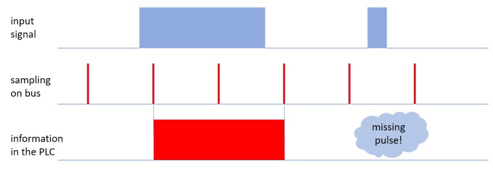
Common input signals are read periodically from the module to the PLC with such a frequency as the number of I/O modules on the bus allows (or the number of queries), the length of the telegrams and possibly the gap between the telegrams. Typically, the signal is restored 1-2 times per second. For some very short signals, however, this may not be often enough and a hazardous situation may occur, which we see in the picture on the right.
 Since the second input pulse "hit" between the two reading moments, the input module returned logic zeros and the PLC did not detect at all that this short pulse occurred.
Some input modules, such as Domat R420, R430, RCIO, RMIO, RXIO, but also MW240 or MW241, also allow these short pulses to be captured and held in the module's memory for reading at the next sampling. Several Modbus registers are used to work with such captured or latched values. Their numbers may be different for different modules, the principle of the function will be shown on the example with a small I/O module MW240. It has two relay outputs and two binary inputs. We will read these inputs using latching functions.
Latch state: Configuration register. We can specify whether the logical 1 - ie the leading edge of the input signal (as in the previous illustration) or logical 0 will be captured. Usually we want to capture the leading edge and therefore it is necessary to specify this setting when configuring the I/O module using ModComTool. and write to the EEPROM. From the program in the PLC, we no longer need to communicate with this register.
Latch enable: Leading edge writing resets the Latched value register and "stretches the trap" again. In order to be able to write a leading edge, a log must be demonstrably written to the register. 0. This is checked by reading according to step (5) in the figure above.

Latched value: The captured value is read from this register, it is actually the memory of the flip-flop.

All digital inputs of the module are bitmapped in the respective register, so that each input can be processed separately. It may seem a bit complicated, but the treatment in the Merbon IDE is not that complicated. We just need to define the appropriate variables (latched value for read, latch enable for read and write) and use a simple function block (or - for a small number of inputs - copy this structure of three functions directly in the program):

The TOF (delayed switch-off) function extends the detected pulse so that it can be safely processed in the application program. Usually 1-2 s is enough. Latched value (LI) and latch enable for reading and writing (LE_read and LE_write) are connected to the block inputs:

The pulse1_out variable already contains the detected and extended pulse from the DI1 input of the MW240 module. During testing, we can then open important values in the graph and see how the pulse, missed by normal reading directly from the DI1 input, is captured and extended in the pulse1_out variable thanks to the latching function.

An example of a project with a prototype of the MW240 I/O module can be downloaded below. In case of questions, please contact technical support at support@domat.cz.