The most frequently used communication driver in the Domat PLCs is Modbus RTU or TCP. It may happen that in larger projects the system limits are challenged, either on the client (PLC) or server side, which can be a sensor, a communication converter, a variable speed drive, a PV inverter or a Modbus TCP / RTU router. Let us have a look how the driver works, and how to optimize the communication if tens or hundreds of devices have to be integrated.
The number of Modbus TCP channels in a PLC is not limited by number of physical ports, as it is at serial (Modbus RTU) communication. Each Modbus TCP channel creates a separate thread in the processor. As the threads are processed sequentially, one after another, it is useless to split the devices into more Modbus TCP channels. It only would slightly increase the overhead for switching between threards, and the communication throughput would not be increased. Unless there is a special reason for it, there should be a single Modbus TCP channel in the PLC where all Modbus TCP devices will be located.
Different devices usually have different IP addresses. Each device establishes a separate TCP connection to its address. The runtime can open up to approx. 15 000 outgoing TCP ports (the operating system allocates ports in the range 49152 – 65535), so there is no limitation here.
In case that multiple devices on the same channel have the same IP address, their queries are merged into a single TCP connection. Thus, the Modbus TCP server is not overloaded with multiple "parallel" TCP connections, which is in accordance with the requirement of MODBUS Messaging Implementation Guide V1.0b (2006), Chapter 4.2, TCP Connection Management:
3) It is recommended for a MODBUS Client to open a minimum of TCP connections with a remote MODBUS server (with the same IP address). One connection per application could be a good choice.
Note that this automatic merging may not occur if one device has a numeric IP address (e.g. 192.168.1.51) and the other has a domain name filled in (e.g. inv1.pvplant.lan), which the PLC would have to resolve - even if to the same IP address - using the DNS protocol.
However, if devices with the same IP addresses were located on different Modbus TCP channels, which - as mentioned above - operate in different threads, this merging does not occur and each thread establishes a separate TCP connection to the corresponding IP address. This could be a limitation for some Modbus TCP servers that will only accept a limited number of TCP connections (for example, only a single one).
Is there any reason to have multiple devices with the same IP address in a project?
Yes, sometimes different variables may be defined in different devices for clarity. For example, for PV inverters there may be a standard device for reading values only (monitoring) and another device with variables for occasional inverter configuration, or for active power and power factor control. For installations where only monitoring is required, only the monitoring device will be used, while for controlled inverters also the devices for control are inserted into the channel.
In what order are queries sent on the bus?
After the program starts, the PLC attempts to open all TCP connections and then sends telegrams for each device in the order (from top to bottom) in which the devices are inserted into the channel. Within a device, since version 2.7.x.x, it is possible to manually specify the order of group communications by changing the Sort Order parameter in the group properties.
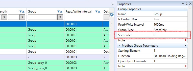
If the Sort Order entries are duplicated (by default, they are all set to 0), the telegrams are sent in the order in which the groups were created.
Although with Modbus TCP it is theoretically possible to open multiple queries (transactions) at the same time and wait for the replies to start coming back, in a PLC the driver is implemented in such a way that in one TCP stream (i.e. in communication to one IP address) the next query is sent only after the reply to the previous query returns. In the following example there is communication with two servers at different IP addresses. Although the IP addresses are not visible in the listing because the port monitor only shows the Modbus application layer and not the whole IP communication (which would be visible e.g. in Wireshark), we can distinguish the servers by different Modbus link addresses: 01 and 03. The column with the link address is marked with a red arrow.
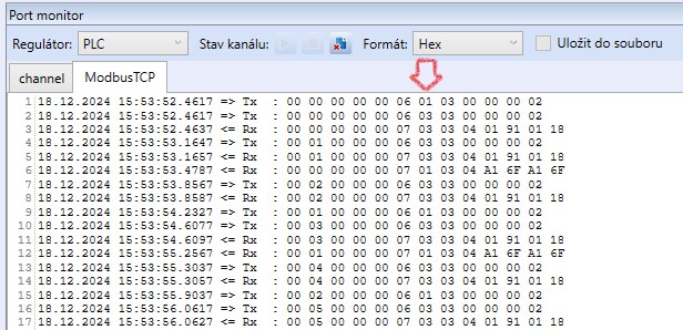
We can see that the Transaction ID series, the first two bytes, is unique for each IP address (i.e., for each TCP stream). In fact, there are two independent Transaction ID sequences in the listing. The query is first sent to the first server (line 1), then to the second (line 2), from which a response is immediately returned (line 3) and thus another query is immediately sent to this server - with Transaction ID 00 01 - and a response is received (lines 4 and 5). Only then does the response from the first server arrive (line 6). However, this is paired with the query from line 1 thanks to the corresponding TCP thread (and Transaction ID).
This rather atypical communication looks like this due to the introduced delay of the first server's response to 1000 ms. In practice, we would only see similar behavior if, for example, one of the servers was located behind a part of network infrastructure that introduced significant latency into the communication.
When communicating with a Modbus TCP / RTU router, it must be taken into account that the serial link does not have nearly the same throughput as Modbus TCP in an Ethernet network. Besides the fact that we must not exceed the maximum number of simultaneously connected clients (which is a feature of the "network side" of the router), it is often necessary to extend the timeout and especially the gaps between telegrams in the case of multiple client connections. This is especially true if we are querying dozens of registers at the same time (it optimizes the bus traffic, but the replies are longer, the packets cannot be "chopped" as much and this increases the risk that there is no time to handle the query before the timeout expires). For example, where 200 ms is sufficient for a single client, when another client connects, the original communication may start to drop out. In Wireshark, the error would look like this:
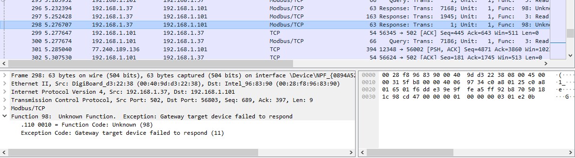
The connection to router (here „gateway“) is OK, some telegrams will get through, but for others the router responds that the Modbus RTU server on the serial line could not be reached.
Increasing the physical baudrate on the serial side, e.g. from 9600 to 115200 bps, usually does not help much. The disadvantages, such as need for reconfiguration, deviation from default values or the risk of problems with longer line lengths, outweigh the possible benefits in the form of shorter telegram times.
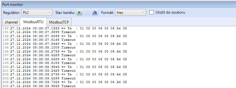
When the Modbus server does not respond, we can see outgoing telegrams - queries at the serial port, but instead of responses the port monitor shows timeouts. This gives us a pretty clear indication that the PLC is sending queries to the serial port, and we can start looking into why the target device is not responding.
In a Modbus TCP channel, the runtime establishes a TCP connection first, and starts sending queries only after opening the TCP channel. So if there are no outgoing queries on a Modbus TCP channel, it may not be a Modbus TCP driver error - just a failure to open a TCP connection. The cause may be the unavailable IP address of the device or a non-functioning Modbus server service, or a wrong TCP port number. It is recommended to check the function of the Modbus TCP server with an independent Modbus client, e.g. ModComTool, Modbus Poll, ModScan, etc. Note that the test Modbus client is usually run on a working laptop and not on a PLC whose driver does not communicate. If the Modbus test client is able to connect, and the PLC is not, check if there are possible security restrictions in the network that block communication between the IP addresses of the PLC and the Modbus server.
The option to set the polling interval can be found in three places:
Channel properties – Pause between telegrams: This parameter controls the actual (physical) transmission on the bus. Queries waiting in the output buffer are sent to the bus at this interval. Telegrams will not appear on the line more often than set here. An interval longer than 0 ms is to be set if the line or the device is unable to process queries in immediate succession for some reason, or if the device needs some time to process the data during a write telegram before it is able to receive the next query. This is usually described in the device documentation.
If the interval is set to 0 ms, the pause between the response and the next query is determined by the PLC capabilities; it is usually 40 - 50 ms. Ideally, approximately 12 - 15 queries per second are transmitted.
Device properties – Read / write interval: The value determines how often queries from groups of this device will be written to the output buffer of the communication driver. The parameter is valid for each group in the device: for example, if there are 4 groups in the device and there is an interval of 1 s in the Device Properties, the device will send 4 queries per second. It can be used if some devices are to be prioritized in communication (output control, inverter limitations) or deprioritized (for example, energy readings from the meter against temperature readings).
Group properties – Read / write interval: Here, the frequency of reading or writing certain groups within the device can be limited to prioritize e.g. reading of rapidly changing current values over the reading of parameters that do not change that often. However, even if the interval is set to 0 ms in the Group Properties, telegrams are not sent more frequently than the restrictions in the Device Properties or Channel Properties allow.
Example: A channel (Pause between telegrams = 0 ms) with one device (Read / write interval = 1 s), which contains four groups. Groups 1 and 2 have the Read / write interval = 0 ms, groups 3 and 4 that of 2 s. In this case, approximately 3 telegrams per second are sent on the bus, the groups are ordered like this:
1 – 3 – 2 – 1 – 4 – 2 – 1 – 3 – 2 – 1 – 4 – 2 – 1 – 3 – 2 – etc.
If the read/write interval for group 4 shall increase to 5 s, the physical frequency of telegrams will not change, only queries from group 4 will be queued less frequently, with a 5 s interval:
1 – 4 – 2 – 1 – 2 – 3 – 1 – 2 – 1 – 2 – 3 – 1 – 2 – 4 – 1 – etc.
Telegrams left out due to longer Read / write intervals are replaced by a "Reading group with index ... skipped" message in the Port monitor.
If there are multiple devices on a channel, queries from all devices are sorted sequentially into the channel buffer.
Example: A channel (Pause between telegrams = 0 ms) with two devices (Device A has the Read / write interval = 1 s, Device B = 0 ms), each Device contains two Groups with Read / write interval = 0 ms.
A1 – A2 – B1 – B2 – B1 – B2 – … – B1 – B2 – A1 – A2 – B1 – B2 – atd.
Telegrams A1 and A2 are repeated appr. every 1 s. The rest of communication is filled by telegrams B1 and B2. There are pauses of about 50 ms between telegrams.
Variables to control communication
The principles described above show that the order in which telegrams are sent cannot be influenced by specifying the communication intervals. The time parameters only affect the frequency of queries. However, sometimes it is necessary to send telegrams either once only or in a specific order - for example, to enable writing to the server when the server requires some "unlocking" telegram before writing, or to read latched values. The commblock and forcecomm variables, which are available for each Group, can be used to control communication:

Remember to enable Autogen first, to map these variables to global variables which can be used in a program.
The commblock variable has a default value of False and if it is set to True, the group stops to communicate. In Port monitor there is a message "Reading (or Writing) group with index ... skipped" again, in the example below for two groups:
02.01.2025 14:26:19.7816 => Tx : 01 03 00 00 00 01 84 0A
02.01.2025 14:26:19.8066 <= Rx : 01 03 02 02 00
02.01.2025 14:26:19.8066 <= Rx : B9 24
02.01.2025 14:26:19.8396 => Tx : 01 03 00 01 00 01 D5 CA
02.01.2025 14:26:19.8696 <= Rx : 01 03 02 00 14
02.01.2025 14:26:19.8696 <= Rx : B8 4B
02.01.2025 14:26:19.8996 Reading group with index 0 skipped
02.01.2025 14:26:19.8996 Reading group with index 1 skipped
02.01.2025 14:26:19.9146 => Tx : 01 03 00 00 00 01 84 0A
02.01.2025 14:26:19.9326 <= Rx : 01 03 02 02 00
02.01.2025 14:26:19.9486 <= Rx : B9 24
02.01.2025 14:26:19.9746 => Tx : 01 03 00 01 00 01 D5 CA
02.01.2025 14:26:19.9956 <= Rx : 01 03 02 00 14
02.01.2025 14:26:19.9956 <= Rx : B8 4B
02.01.2025 14:26:20.0346 Reading group with index 0 skipped
02.01.2025 14:26:20.0346 Reading group with index 1 skipped
It is more complicated with the forcecomm variable. It is used to trigger communication (to put the telegram into the buffer), but the read/write interval takes precedence here: if the read/write interval is set to 20 s for example and the forcecomm variable changes to True, the write will be performed after 20 s.
The forcecomm variable should be used so that forcecomm is permanently set to True. When the program is running, commblock = True and thus this group’s communication is disabled. The moment commblock is changed to False, the telegram is sent regardless of the read/write interval. Thus, a descending edge brought to commblock causes the telegram to be sent. The state of the commblock must be returned to True before the time to which the read/write interval of the corresponding group is set to avoid periodic sending of the telegram (unless this is desired).
The function of the forcecomm variable is that if set to True, then after the group communication is released by setting commblock to False, the telegram is put into the buffer immediately rather than after the read/write interval has elapsed.
A more detailed understanding of how the Modbus driver works and what its individual parameters mean will make it easier not only to optimize the program, but also to find errors if everything does not work on the first attempt. If you have any further questions, please do not hesitate to contact technical support at support@domat.cz.
