The measurement of differential air pressure in air-handling equipment is most often encountered when monitoring the clogging of filters or the operation of fans. There, two-state measurement and evaluation using differential manostats will suffice. In variable air volume systems (VAV) however, the air-handling unit usually has the task of maintaining a constant pressure on the supply, exhaust or between. This requires continuous measurement, which is what differential pressure sensors are used for. When assembling and commissioning, it is good to follow a few simple rules, which we will remind you of in the following text.
Sensor type and range selection
The maximum measuring range should be determined by the designer based on the expected highest required pressure value. We always choose the type of sensor with the nearest higher range, it is ideal when the regulated value is around 60-70 % of the sensor's maximum measuring range. At the same time, we must pay attention to the resistance of the sensor against overloading - we check that the maximum differential pressure must not exceed the value specified by the manufacturer, otherwise the sensor could be damaged. Fortunately, these highest permissible pressures are multiples of the measuring range of the sensor, e.g. S+S PREMASGARD® 212x-SD with a max. measuring range of 0...1000 Pa can withstand an overload of up to 50,000 Pa. This is a pressure that cannot be reached in the unit under normal conditions, but we must also take into account possible pressure surges arising during transient states.
Some sensors have switchable ranges, which makes the work easier for the designer, but slightly more complicated for the technician on the construction site: it is necessary to check that the sensor range is set according to the data in the project.
When regulating the differential pressure of clean spaces compared to the surroundings (grey zone, corridor, etc.), it is necessary to realize that the regulated value will be very small, typically 2 to 5 Pa. That is why we avoid sensors with an unnecessarily large range. For example, if we used a 0...100 Pa sensor, the operating value would be approx. 3 % of the measuring range. This is on the one hand comparable to the measurement error (which is 3 Pa for this range), on the other hand the signal of a sensor with an output of 0...10 V has a size of only 300 mV and is therefore more subject to interference. It is therefore necessary, even at the cost of higher costs, to choose a 0...25 Pa sensor that has an accuracy of ± 1 Pa.
Selection of locations for the sampling probes installation
Choosing the location for mounting the probe is probably the most critical point of the entire process. In the following figure we see typical measurement cases:
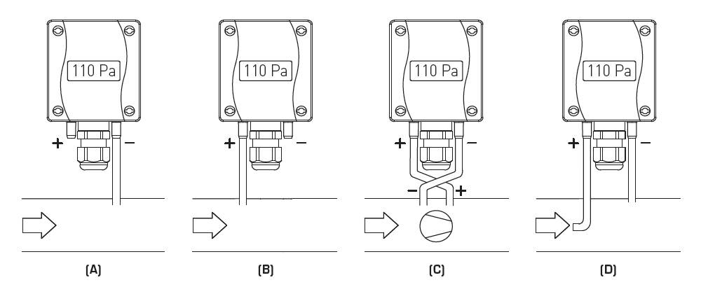 Typical cases of installation of a differential pressure sensor in the air handling unit.
A – the negative pressure measurement in the AHU compared to the atmosphere, typically when regulating to a constant pressure on the exhaust
B –the excess pressure measurement in the AHU compared to the atmosphere, typically when regulating to a constant supply pressure
C –the differential pressure measurement on the fan (source), there is the excess presure downstream of the fan
D – the dynamic pressure measurement, on the + port there is a tube for sensing the dynamic pressure, on the – port there is the static pressure in the pipeline
It is preferable to install the probe in the pipe rather than directly in the unit. In the duct, the air flow is smoother and the vibration of the unit is not transmitted to the sampling tubes or the sensor itself. The recommended distance from elbows or other disturbing elements, the so-called calming length, is six times the diameter of the pipe. For pipes with a rectangular cross-section, the so-called equivalent diameter d applies.
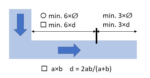 Installation of the probe relative to the soothing length.
If the HVAC supplier equips sampling points, these are used to measure HVAC during regulation. If we want to use them, it is necessary to adjust the tube with a T-piece, plug the service intake and use the other port for regulation. In the case of air ducts that are divided in shape, we must make sure that the sampling point is not in the corner of the pipe or in another place where the pressure cannot be measured correctly.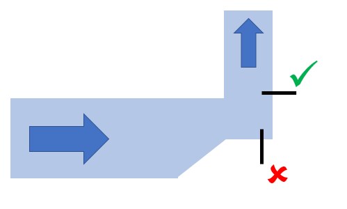
Inappropriate and more appropriate collection point.
It is clear that it is not always possible to observe the cooling-off length. Then we have to verify the correct function of the sensor and, if necessary, ask for the cooperation of the air-handling supplier before he leaves the building.
The problem can arise with air-handling systems that have the fan installed directly next to the ventilated space (missing supply or exhaust pipes). To measure the pressure in the room, we must use special probes suitable for mounting in installation boxes under the plaster, which are located in a ventilated area.
Length and cross-sections of supply pipes
A two-meter PVC tube with a diameter of 6 mm is included with the S+S PREMASGARD sensors. The tube is divided and possibly shortened so that the connection between the sampling point and the sensor port is not unnecessarily long, but also not stretched or bent (which could reduce the effective diameter of the tube). If the sampling points are more than 2 m apart, it is possible to use a longer tube, up to a length of approx. 10 m. For longer distances, it is necessary to use a tube with a larger diameter (10 – 12 mm), but it is better to avoid these situations. Among other things, the longer the tube, the longer the response of the sensor to pressure changes.
If the air handling unit is installed in an outdoor environment and there is a risk of condensation when measuring on the exhaust, make sure that the tubes are always sloped in the direction from the sensor to the sampling point. This will prevent condensate from accumulating in the sensor or bending the tubing - frozen condensate results in the sensor not working. Mere thermal insulation of the tube is not an effective measure, moreover, the tube may be pinched by the insulation.
Commissioning procedure
First, we check the mechanical and electrical connections. The sensor should be easily accessible, the tubes must not be pinched by the insulation. The hose connections must be firmly attached to the pipe to seal. The wires inside the sensor must not interfere with the internal tubes that connect the input ports of the sensor with the measuring element, pay particular attention to the wires inserted under the printed circuit board. It must not happen that after putting on the cap, the reset button is pressed with a compressed wire, etc. If necessary, it is better to shorten the supply wires than to force them into the electronics compartment.
Next, we set the switches on the printed circuit board according to the desired range and function. With S+S PREMASGARD sensors, the reaction is immediate, the sensor does not need to be disconnected from the supply voltage for the setting to take effect.
We check if the sensor shows a zero value without pressure. If not, we reset the sensor:
In the application program, we check that the scaling of the input signal corresponds to the set measuring range. Attention for symmetrical measurement (-X... + X Pa), the signal at zero differential pressure is 50 % of the signal range, i.e. for sensors with a voltage output of 5 V.
In cooperation with the air handling supplier, we will verify that during operation the sensor shows the same values as those measured by a portable differential pressure meter.
If the measured value fluctuates significantly, for example due to structure vibration or air turbulence, we can set the measurement interval directly on the sensor (DIP switch 5, switches between 1 and 10 s) or introduce filtering in the software (e.g. in Merbon IDE block B86):
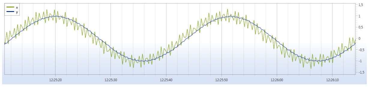
Software filter. x = input value, y = filtered value
Regulation and setting of PI controllers
We set the proportional and integration constants in a similar way as for other regulated circuits. First of all, it is advisable to realize what pressure the fan set at maximum speed will develop (usually scaled in the control program as "100% of the control signal" - we are not too interested in the absolute value of the speed or frequency, this is set by the air handling supplier on the frequency converter). In principle, this should be the bandwidth, the so-called P constant. First, we regulate the system only as a P controller, with an integration constant equal to 0, and make sure that the system does not oscillate - if it does, we gradually increase the bandwidth, otherwise we decrease the bandwidth to the oscillating limit, and then add approx. 10 %. Then we introduce the integration component and try to achieve a permanently accurate required value while maintaining the stability of the system.
Example – overpressure in the production hall, clean rooms:
For overpressure regulation with a required value of 3 Pa for a clean space with a volume of several hundred m3, the pressure is measured as the differential between this production hall and the surrounding environment (a large hall without demands for air cleanliness). A sensor with an output of 0...10 V and a range of 0...50 Pa was used. As a default, a bandwidth of 16 Pa was chosen and after regulation, an integration constant of 400 s was set. It is therefore a fairly damped regulation circuit. This seemingly long integration time prevents fluctuations in regulation when the door is opened after people enter the room, because the open door causes a temporary sudden drop in pressure. The regulation should not react to it at all - anyway, it is not in its power to compensate for the decline so quickly and to such an extent.
Example – HVAC for supplying a VAV system:
Supply and exhaust are regulated separately, always relative to the atmosphere (situations [A] and [B] in the picture above). The required value on the supply is 370 Pa, on the exhaust 360 Pa. Sensors with a range of 0...1000 Pa are used. The bandwidth is 1000 (input), or 800 (extraction) Pa, integration constant 40 s. Note that the integration constant is an order of magnitude smaller than in the previous case – this is not about measuring the pressure in a large area of the hall, but about sensing the pressure in the pipeline at a distance of approx. 5 m behind the fan. The changes will therefore take effect almost immediately and the circuit is better regulated than in the previous case. During commissioning, in cooperation with the HVAC supplier, the desired pressure value was gradually increased until the moment when even the most distant VAV box had the pressure necessary for its proper functioning. This value was then set as desired.
Example – HVAC for clean rooms:
The ventilation system supplies the system of clean, gray and dirty spaces in the operating wing of the polyclinic. The system consists of an HVAC unit supplying the entire system and several zone regulators that ensure pressure differences in the order of Pa units between individual rooms. The air supply is regulated to the desired differential pressure value of 140 Pa relative to the atmosphere according to situation [B] in the figure above. The system was regulated with an integration constant of 900 s and a bandwidth of 60 Pa. The constant 900 s is perhaps unnecessarily long, but it managed to achieve greater regulation stability and tolerance to pressure surges that occur when the door is opened when people pass between zones - the controller does not needlessly try to compensate for such sudden changes, which would anyway failed. A bandwidth of 60 Pa does not follow the above procedure, but works empirically; failed to ascertain how the frequency converter is set here. In steady state, the output signal for the frequency converter has a value of 62%, the actual value is approx. 140 +/- 8 Pa.
Air conditioning supplies clean spaces and the air is gradually transferred to gray and dirty spaces. Damper regulators in the pipes connecting the rooms measure the differential pressure between the rooms. They are set to a desired value of 5 Pa, bandwidth 30 Pa, time constant 120 s.
All the above-mentioned values of the control constants serve only for orientation, in no case can they replace the proper regulation of a specific device.
