When deploying room units UI011, room controllers UC/FC..., as well as 3rd party devices talking Modbus, there appears a problem how to write into variables which are also controlled locally – over a knob, touch schreen, or other manual control.
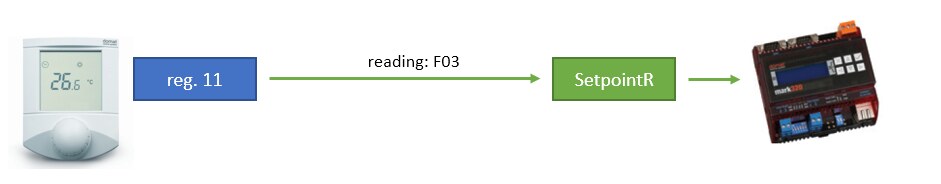
Letְ’s take a UI011 room unit as an example: Reading into the PLC is straight and clear. The PLC requests data from the server periodically, and its communication driver writes the value into a global variable:
Configuration of a variable just to write to the device is also not so difficult:
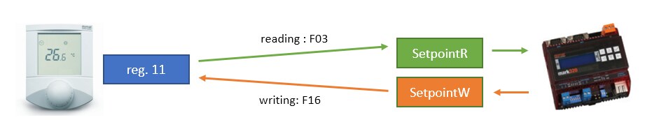
However, as soon as the value shall be set both ways (i.e. over the knob and over the web interface of the PLC), there is a problem: a web command controls the variable to write, but this variable does not reflect changes executed over the knob on a local basis. This means that the web user does not know if the variable had changed in the meantime. It would have to be displayed separately. Even then, another problem is when the value has to be set incrementally, e.g. „set the temperature by 0.5 K higher“. To achieve this, the value to write must be refreshed by the actual value which is manually set in the room unit.
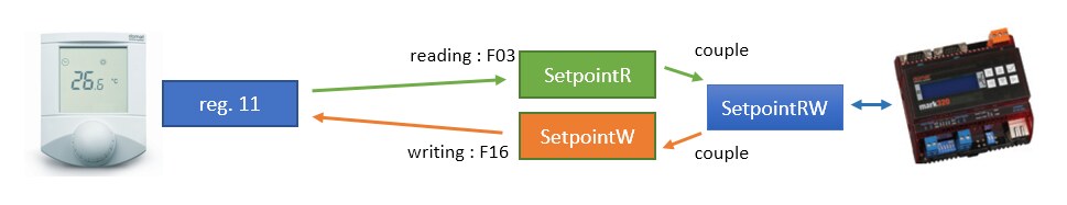
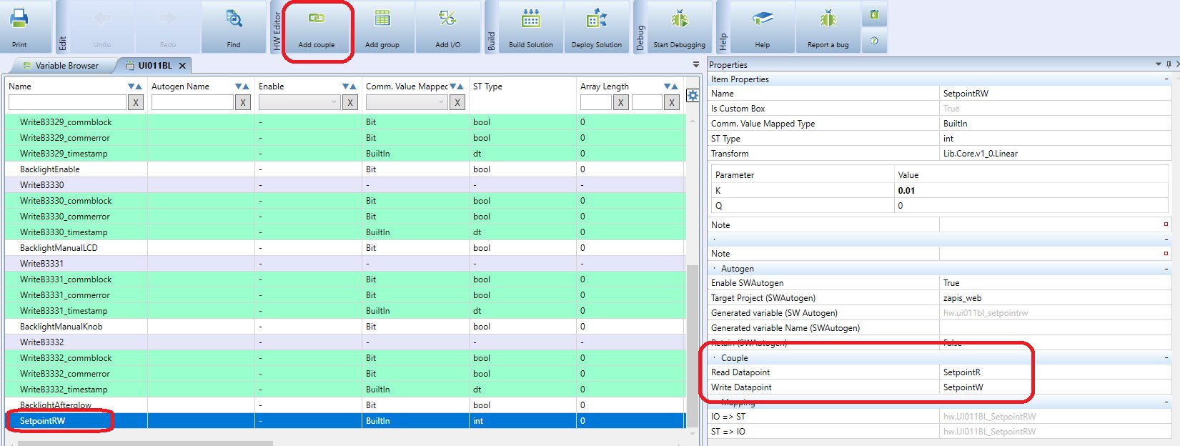
Therefore it is useful to create a variable which allows both to update its value from the room unit, and to write its value into the room unit on change. This can be achieved by a so called couple, or connection of two hardware I/O data points. A couple also represents a global variable.
The group containing the variable to write must be set as Write on changes only.
The SetpointRW variable is then used both to display and to set in a LCD menu, web pages etc., in the same manner as if it was a common global variable containing a setpoint.
See more screenshots and configuration proceedings including notes to the Autogen function in the Merbon IDE help. Search for „Coupling I/Os“ in the Index.
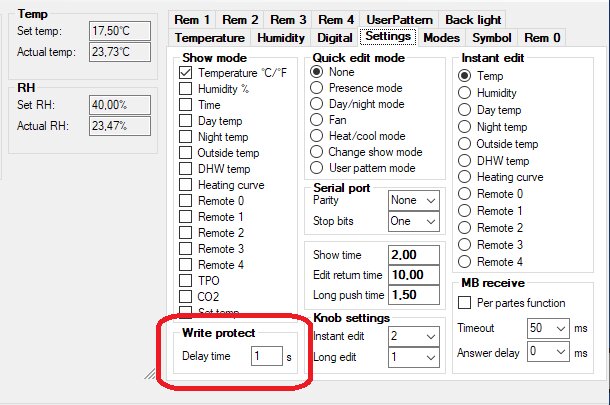
Its default value is 10 s. It is a time during which the writing to registers is blocked after each manual intervention (using the knob). The aim is to prevent unintentional overwriting of a value over the bus after manual change, before the value could be read (updated) into the PLC and rewritten back to the room unit. This issue is relevant only at PLCs where the programmer is not able to control the writing process of the communication driver. If Write only on changes is used in Merbon IDE, this setting should not be relevant.
