DID induction units (DID = Deckeninduktionsdurchlass, ceiling induction diffuser) have recently been a popular choice for designers where variable air volumes are used to control carbon dioxide or air quality using a mixed gas sensor, while the air needs to be reheated or cooled. They have an advantage over fan coils, for example, in lower maintenance requirements and lower acquisition costs. In terms of measurement and control, however, they bring some requirements, without which their intended function cannot be guaranteed. However, building management system suppliers may encounter a task that conventional pre-programmed fan coil controllers either do not optimally or at all do.
The Domat FCR015 zone controller with UC015 room controller for CO2-based heating, cooling and air flow control comes with new firmware. It was developed mainly for more flexible manual output re-adjustment. More interesting in terms of DID control is the possibility to assign logically output sequences from PI controllers for heating, cooling and air volume. A very powerful tool is the use of combinations of these sequences.
The controller has three analog outputs 0… 10 V and two triac outputs (24 V AC on/off or PWM). Each output can be independently controlled according to several output sequences:
If we enable several sequences at the same time, the output signal always corresponds to the largest one.
It is thus possible to solve for example the connections that have recently appeared in office and residential buildings with a single controller.
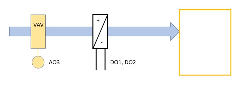
>This is not yet an induction unit – in this connection, the VAV controller is controlled by a request 0… 10 V to 0 … 100 % of the nominal air flow. In Comfort and Decrease modes, a minimum air flow rate is ensured, which can be set as one of the controller parameters, and therefore heat or cold transfer from the heating or cooling register to the room is ensured. In Off mode, the airflow requirement is 0. The configuration can be used even if the air-conditioning system is used only for cooling (or for reheating only) and heating (or cooling) is handled by a radiator (or cooling beam).
 VAV damper, heating / cooling (typical connection for air quality control)
>In the summer of 2019, one of the projects implemented included the following connection: a combination of a VAV controller and a fan coil, which was to provide heating and cooling. The advantage is that if the room air quality is satisfactory and the VAV requirement is minimal, there is no supply of fresh air (or the supply is kept at the set minimum) and the circulation fancoil only compensates for heat loss (or in case of cooling gains). The circulation fan is controlled continuously according to the requirement for heating or cooling.
VAV damper for CO2, circulating FCU for heating / cooling
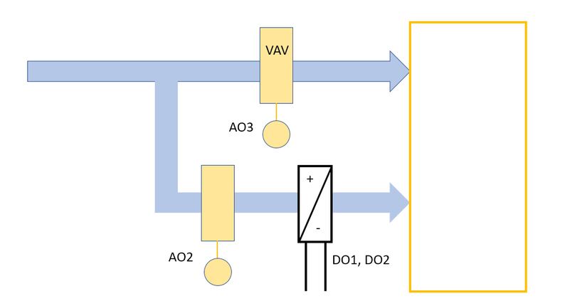
>The induction unit is already installed here. Its proper function depends on a certain minimum supply air flow rate, typically from 20 m3/h; if the flow rate is too low, there is no required heat transfer between the heat exchanger surface of the register and air as the transfer medium. The AO3 output, the signal for VAV box control, is controlled according to air quality. The damper controlled by the AO2 outlet has basically two positions: it is fully closed when there is no heating or cooling demand and opens fully when the heating or cooling demand exceeds 5 %. Only full air flow can ensure the required efficiency of the DID system.
 VAV damper for CO2, DID system for heating / cooling
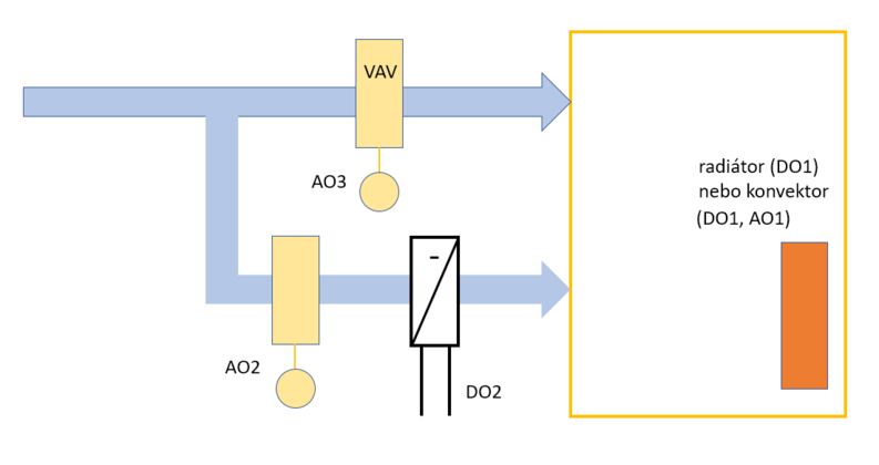
>In the extended variant of the previous circuit, the air quality control is the same, while the DID unit only provides cooling. The AO2 output opens fully when cooling is required, the PWM signal at the DO2 output modulates the cooling valve for accurate temperature. For heating is then used a radiator with a thermostatic valve controlled by 24 V PWM signal at output DO1, but it would be possible to use a convector (sometimes called Dynamic Boost Radiator, DBE) with forced air circulation by EC motor, which is controlled by the signal 0… 10 V from AO1 output.
 VAV damper for CO2, cooling DID, heating by radiator or convector
The controller is always in one of the operating modes: Comfort, Standby or Off. The different modes differ from each other by the required temperatures for heating and cooling, which allows us to define the dead zone when needed, and the air volume requirement for the VAV box: in Comfort mode the flow is controlled according to the CO2 level in the room flow rate adjustable as internal parameter – and in Off mode, 0 V is supplied to the VAV box.
The operating mode changes either according to local conditions such as presence sensor, window contact or user settings, or remotely from the central office, or according to a time program controlled by a real-time clock directly in the controller. The FCR015 controllers, like all other FCR… controllers, offer open Modbus RTU communication over RS485 and are ready for integration into any building control or visualization (SCADA) system. For details, see the updated Modbus table and FCR015 datasheet at Download section.