From time to time in implementations we come across active sensors with a current output of 0...20 or 4...20 mA. How to correctly connect them to the analog inputs of the I/O modules?
The current loop standard arose in response to the demand for a robust analog signal that would be easy to deploy, allow signal transmission over longer distances, and be immune to interference. A sensor with a current output therefore represents a current source with a value that is proportional to the measured quantity. At first, the 0...20 mA signal was used, later the 4...20 mA standard became established. The non-zero quiescent current makes it possible to easily detect the interruption of the measuring loop, i.e. the loss of the signal, which could be confused with the measured value at the lower end of the range in the 0...20 mA range.
We come across sensors with a two-wire connection, which are inserted into the power supply circuit and actually limit the current that flows through them, and sensors with a three-wire connection, which have separate power terminals and a separate output terminal, which represents the source of the signal current against the ground. Sensors are usually powered by an external 24 V DC source, manufacturers usually allow a wider voltage range, e.g. 24...36 V DC. If a few basic rules are followed, this source can also be used to power I/O modules, although it is recommended to power the I/O modules from a separate 24 V AC transformer.
Both types, two-wire and three-wire sensors, can be connected to the input modules. The corresponding input must be set as current using a switch (e.g. R560, RCIO modules) or a jumper (e.g. RXIO, markMX). Attention, for some inputs it is not possible to use a current loop - the inputs are not equipped with the necessary input circuits. Check already during planning in the catalog sheet that the respective input really supports the current range.
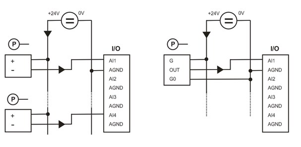
For a two-wire sensor, both the module and the source must have a common ground so that multiple sensors can use the source at the same time. This is implemented at the AGND (or AIC, depending on module type) and 0 V connection point.
 One source can therefore supply multiple sensors. We just have to make sure that the sensor is always connected with the positive wire to the positive pole of the source and the negative wire to the positive pole of the input. It is also a good idea to verify the sufficient power of the source: one sensor at full signal consumes approx. 2 VA.
For three-wire sensors, the current output signal comes from the OUT sensor output and flows through the AI input to the ground potential G0 / 0V, i.e. to the power source. The arrows show the direction of current flow. The connection is therefore similar to that of voltage sensors.
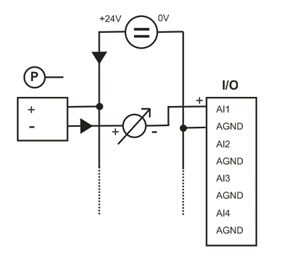
Another case may arise when there is to be another panel indicator input or existing measurement system in the circuit. The connection then looks like this:
 But watch out for the negative pole of the input of a foreign system. It must not be connected either to the power supply ground (0V) or to the signal ground. If this were the case, connecting one sensor to two measuring devices (inputs) is not possible. The same applies to three-wire sensors: the output of the sensor and both inputs of the measuring devices must be connected in series so that the same measured current flows through both inputs.
Let's not forget to correctly set the input range to 0...20 mA in the software and enter the conversion constants in the transformation. Rather than a linear transformation, a two-point transformation is preferable:
This is because it allows you to easily and clearly set the upper and lower limits of the measured range, especially for the 4...20 mA signal. The example above shows the input setting for a differential pressure sensor with a measuring range of -50...+50 Pa. The input values are in uA (so they come to the program from the input modules).
For the linear transformation "Kx + Q", for example, for a pressure sensor 0...20 mA with a range of 0...6 bar, K = 6 / 20000 = 0.0003 and Q = 0, for a humidity sensor with a range of 4...20 mA 0...100% we get the coefficients by solving the system of two equations for 4 and for 20 mA:
0 = K*4000 + Q
100 = K*20000 + Q
This will give K = 0.00625 and Q = -25.