Air handling units (AHUs) and air conditioning systems with integrated controls are becoming more and more popular. Their strong point is mainly that the control system with control algorithms is supplied by the manufacturer, who should know how the plant shall be controlled, and who could tune up the algorithms at dozens of identical units at different projects. Installation of the peripherals is also simpler, as most of them can be wired already in the production works, and complicated installations on site can be avoided. On the other hand, a link to the building management system (BMS) or SCADA, which also integrate other technologies, is required. The AHU supplier thus should be a qualified partner for the BMS supplier, who is responsible for this integration.
 There are more communication standards used today. Each of them requires a slightly specific approach. Let us take Modbus RTU (over serial line) or Modbus TCP (over Ethernet), one of the most favourite protocols, as an example to show the whole process and point out the most common problems.
Even in the design phase it is necessary to specify the main facts which affect the whole supply and commissioning process:
The AHU supplier must specify if the controller talks over serial line (typically RS232 or RS485) using Modbus RTU, or over Ethernet and Modbus TCP. There are Modbus TCP/RTU routers to convert data from Modbus over serial to Modbus over Ethernet, but these are extra components in the system, which must be supplied, installed, commissioned and paid. Therefore it is advisable to get along without them, and if they are required, the designer should specify who will be the supplier and who will be responsible for their commissioning and setup.
It should be also cleared that if the unit needs a communication card or external interface, these components are part of delivery. Some manufactures use a single interface for more units, which may save costs.
An Ethernet card must have its IP address configured. Definition of the IP address range and assignment of addresses to the units is usually done by the BMS supplier, or IT department of the final customer in a corporate network.
If an air-conditioning unit or its communication card features a serial line, learn in advance what kind of physical interface it provides. For direct link of two devices and shorter distances up to 15 meters, the RS232 may be a suitable standard, while for longer distances up to 1000 m and more units on the bus the RS485 line is used. In either case it should be checked if both communication parties are able to work with the same communication parameters (baudrate, parity, etc.).
The design documentation should be as detailed as to terminal description, which means that the AHU supplier should provide documentation with terminals numbering and other bus requirements, such as shielding, termination, maximum bus length, maximum number of units on the bus etc. Most of the data are available over the Internet. However, it must be known what interface or communication card type is used, as some manufactures offer more communication solutions.
The Modbus protocol describes two roles: master and slave. There is always one device on the bus as a master, usually the supervised PLC or SCADA, which controls the communication and polls the slave unit or units. The supplier of the slave device must provide a Modbus table with the list of variables, similar to that below. The roles also may be called client and server. Before the commissioning starts, you should attempt to get as much information as possible: Modbus tables, data sheets, hints on specific features from the supplier. Record the important facts for next similar projects in the project documentation or in your special know-how folder. All settings should be updated in the actual project documentation: this makes life easier for the service staff. If the supplier offers lending of his devices in advance, do take the chance for this hands-on experience. A hour in the office equals to several hours on site.
When commissioning, go step by step, from bottom to top, and always check if the previous parts are completely OK. It makes no use to start up the whole system and then randomly seek for bugs. With serial communication over Modbus, the steps are as follows:
As a next point, try to establish (any) communication with the slave device. Use simple programs – utilities, which offer more flexibility than a preconfigured PLC project. Anyway, there may be a bug in the PLC project, which would only be confusing. The proceeding is as follows:
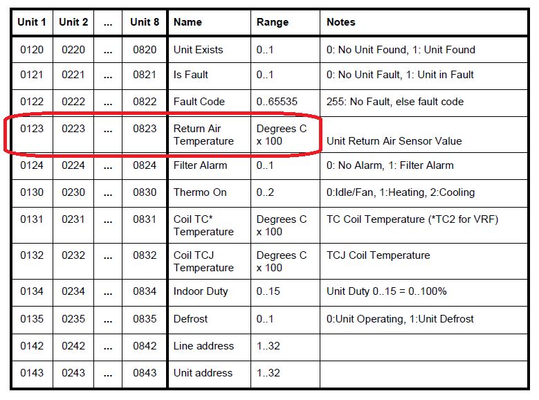 Fig. 1: Modbus table for FDP3 interface (Toshiba aircon units)
The most common issue. Check the Hardware points above, especially the setup of communication parameters. If they are not known, try the ModComTool utility and its scanning function which automatically tests all combinations of selected communication parameters, and stops at the moment when a response is received.
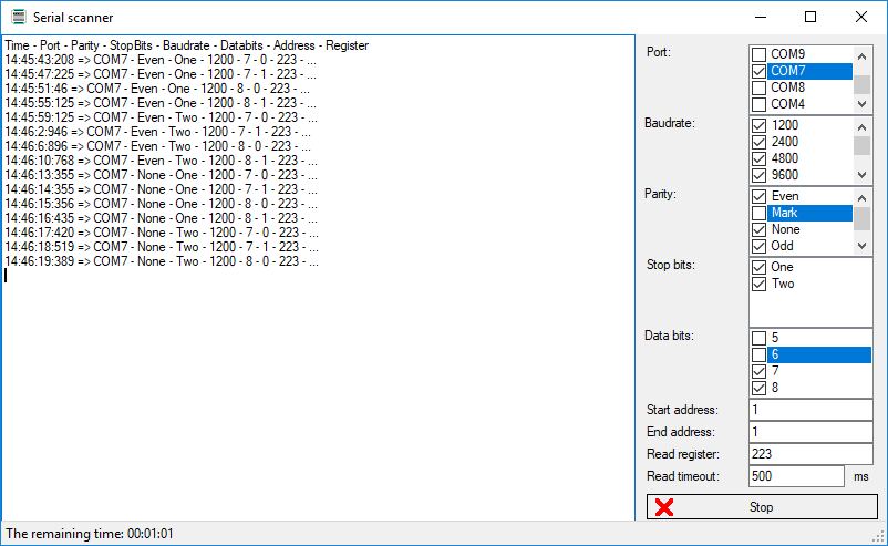 Fig. 2: ModComTool scanning utility
In the utmost case, the device supplier can be asked to „select his favourite weapon“ and show that his device responds on a Modbus request using any Modbus client program, even his own utility. If he is able to prove this, the problem is on your side. The LEDs indicating sent and received data may help, you can at least see if the master sends some data, and if the slave is responding or not.
With TCP communication check if the Modbus port number is set to 502 in the device, and you can try to change the Modbus (link) address in the request. The device should ignore the Modbus link address in the TCP request according to the Modbus standard, but devices were noted where the Modbus server required the link address of 1, otherwise there was no response at all. Another interesting reaction was found at the Advanced Energy photovoltaic inverters, which responded to link address 1 for reading, but link address 0 had to be set for writing. The manufacturer explained this as a protection against writing by mistake, a security by obscurity measure.
If a standard Modbus error is returned, usually the request was sent using an unsupported Modbus function (e.g. Read Holding Registers F03 rather than Read Input Registers F04) or there was a non-existing register number queried – this might have been caused by misinterpreting HEX and DEC formats (e.g. 200 hexadecimal is 512 decadic; if the table is in HEX and the value is entered as 200 into a DEC-based client, it is a completely different register which is queried). Note also that the notation „40012“ mostly does not mean „register 40012“, but „register 12 read by function F04“ (or even „... read by function F03“, which is interesting and deceiving at the same time).
If the received value is completely different from the expected one, such as 0 rather than 21, most probably another register is read. Some manufacturers start the Modbus table numbering with 1 (as registers), some with 0 (as addresses). Try to increase or decrease the register address by 1. You can also read a whole block of registers at a time, and easily tell which value belongs to which variable. However, it may also be that another Modbus function is used (e.g. F04 rather than F03) and completely different data are read! Remember also that at values below 0 (such as outside temperature) the underflowing of the Word format causes e.g. -1 to be read as 65535.
This means that you are on the right way and the problem may be in scaling only. The result must be divided, mostly by 10 or 100: Modbus can not communicate decimal numbers. Values for which decimal resolution is required must be multiplied in the server prior to transmission, and divided after reading by the client. The manufacturer should mention this in the Modbus table, such as at Fig. 1 where the temperature is stated in °C ×100. It must thus be divided by 100 after reading to get the correct value.
As soon as the first value is communicated successfully, half of the work is done. Other variables usually keep the same rules. Similar method is used for writing, just note that to enable writing it may be necessary to set a particular value in another register – this is used to protect the device from unintentional writing. Such tricks should be advised of in the device manual or Modbus table.
Data integration not only saves physical datapoints in the control system, it also makes easy to communicate values which would be difficult or impossible to transmit over analogue signals. These are mainly energy consumptions, operating hours (cumulated values), numbers of alarms, alarm codes, and other discrete multistate values.
For those who are interested in more details, Domat organises free trainings where the participants put their hands on the communication and even can try to integrate their own devices. A properly designed and commissioned link between two systems brings a transparent view on technologies, and may increase comfort in buildings and cut down service costs.
