A detailed description of analog input and output settings and the meanings of all parameters can be found in the Merbon IDE help, section Controller (PLC) - Transformation and configuration of analog inputs. Here we will just summarize the procedure and common mistakes:
According to the type of input signal, select its type for each input:
Another range "Pt1000 temperature (-50 ... 150 °C)" means that linearization (conversion of resistance to temperature) already takes place in the I/O module and the temperature * 100 (°C) is transmitted to the PLC via the bus - see Modbus table eg RCIO module. We can use this option if we use the I/O module for data collection in third-party systems that do not allow linearization in PLC - just divide the value from the bus by 100. In Merbon IDE, however, it is more advantageous to linearize only in PLC etc.
Common mistake: The module is set to the range "Temperature Pt1000 (-50 ... 150 °C)", the transformation Resistance to temperature is also set in the IDE... The value, which already represents the temperature numerically, is processed by the linearization curve "resistance → temperature" for the second time and thus gives a meaningless result, -247 ° C.
The coefficients Pre_K and Pre_Q are used before the transformation, Post_K and Post_Q after the transformation:
The Pre ... transformation is used both to convert the Modbus value to a resistance, and it can be used to compensate for the line resistance between the sensor and the I/O module. The Post ... transformation is used to compensate for the measurement error of the sensor itself and is entered in K.
Diagnostic tip: The value that enters the PLC via Modbus can be read in Debug mode in the hw_hidden namespace:
For AI01, it is 1110.6 Ω, which is the correct measured value (corresponds to a temperature of 28.4 °C). According to this value, we know whether the problem is in the I/O module settings or in the code in the PLC.
Therefore, the correct setting for the passive Pt1000 sensor looks like this:
![]() The type of transformation, here Pt1000, selects the linearization curve - it is specific for each type of sensor (Pt100, Pt1000, Ni1000-5000, etc.).
The type of transformation, here Pt1000, selects the linearization curve - it is specific for each type of sensor (Pt100, Pt1000, Ni1000-5000, etc.).
Common error: The Pre_K coefficient is set to 1. It must be 0.1, because the resistance value is transmitted "Ohm * 10" on Modbus to maintain a reasonable resolution:
 Settings in the I/O module
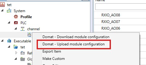
It is also necessary to configure the measuring ranges in the I/O module. This can be done either in the ModComTool program when addressing and animating I/O modules, or - more preferably - in the Merbon IDE by right-clicking on the I/O module and selecting Domat module configuration.

In newer version of Domat IDE use Upload module configuration
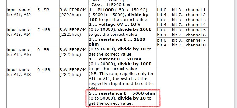
These ranges are listed in the Merbon IDE help for each I/O module and in the Modbus map of the respective module.
Common mistake: This module setting is not performed, the module then measures with the default or old input range and the calculated values in the PLC do not make sense.
Probably the best transformation for the range 0(4)...20 mA is a linear two-point transformation.![]() The figure shows an example of the setting for a pressure sensor 0...20 mA = 0...600 kPa. The input and output range can be seen at a glance. For sensor 4...20 mA = 0...600 kPa, only the value X1 = 4000 would change.
The figure shows an example of the setting for a pressure sensor 0...20 mA = 0...600 kPa. The input and output range can be seen at a glance. For sensor 4...20 mA = 0...600 kPa, only the value X1 = 4000 would change.
As in the previous case, of course, a simple linear transformation Kx + Q can be used:
![]() Both transformations give the same results, but the coefficient K = 60 = 0.001 * 600 (conversion of mV to kPa) is at first glance less understandable than the two-point transformation (X1...Y2) on the left.
Both transformations give the same results, but the coefficient K = 60 = 0.001 * 600 (conversion of mV to kPa) is at first glance less understandable than the two-point transformation (X1...Y2) on the left.
All values related to the setting of inputs, transformations and their coefficients will be applied only after uploading and cold restart of the program. During commissioning, a cold restart (in which the current values from the runtime are lost and all variables are set to the default values from the source code) is not a problem. Later in operation, however, we want to keep the current values, ie avoid a cold restart. Then you can proceed as follows:
With the Identity transformation, auxiliary variables with the type of linearization, coefficients, etc. are deleted during compilation. Their re-establishment already applies new values. If we only changed, for example, the type of linearization curve or the values of Pre_K, Pre_Q, X1, X2, etc., the transformation would always remain in the code and after uploading the program and warm restart, the current (old) values in the PLC would be used.
Common mistake: After changing the transformation coefficients, the PLC does not perform a cold restart. Therefore, the old transformation is still valid and the PLC displays meaningless values.

